Method of joining a pressure sensor header with an associated transducer element

a technology of transducer and header, which is applied in the field of pressure transducers, can solve the problems of affecting the operation of the header, the welded joint at the header-port interface, and the pins and other header components, and achieves the effects of improving the efficiency of the header, and improving the accuracy of the header

Inactive Publication Date: 2005-11-10
KULITE SEMICON PRODS
View PDF16 Cites 35 Cited by
  • Summary
  • Abstract
  • Description
  • Claims
  • Application Information

AI Technical Summary

Problems solved by technology

Such deep welding processes usually produce localized heat in the header material, which may stress or crack the glass header seals, pins and other header components.
However, these conventional pressure sensor header to port joining methods still present various problems.
The extreme external pressures tend to fatigue and fracture the welded joints at the header-port interfaces.
Additionally, as described above, the weld heat during the joining process tends to heat and damage the glass seals.
The provision of larger or longer headers to avoid such weld damage may result in more costly, heavier or less accurate pressure headers.

Method used


Image

  • Method of joining a pressure sensor header with an associated transducer element
  • Method of joining a pressure sensor header with an associated transducer element
  • Method of joining a pressure sensor header with an associated transducer element

Examples


Embodiment Construction

[0020] It is to be understood that the figures and descriptions of the present invention have been simplified to illustrate elements that are relevant for a clear understanding of the present invention, while eliminating, for purposes of clarity, many other elements found in typical pressure transducer headers and manufacture methods relating thereto. Those of ordinary skill in the art will recognize that other elements are desirable and / or required in order to implement the present invention. However, because such elements are well known in the art, and because they do not facilitate a better understanding of the present invention, a discussion of such elements is not provided herein. The disclosure herein is directed to all such variations and modifications to such elements and methods known to those skilled in the art.

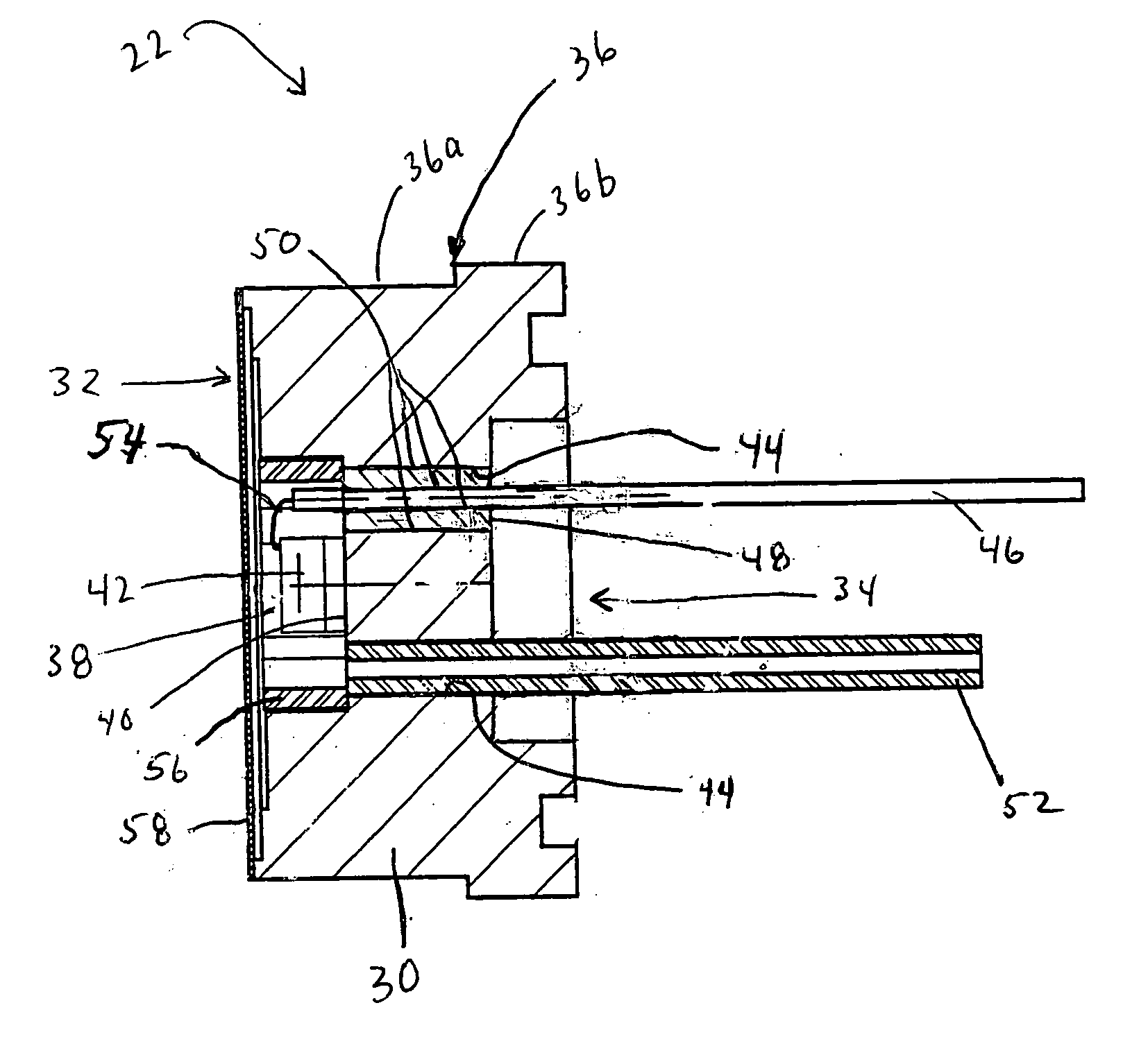
[0021] Referring now to FIG. 2, there is shown an illustrative embodiment of a pressure transducer assembly 20 according to an aspect of the present invention. The...


PUM

PropertyMeasurementUnit
hydrostatic pressuresaaaaaaaaaa
pressuresaaaaaaaaaa
hydrostatic pressureaaaaaaaaaa

Abstract

A pressure transducer assembly including: a pressure sensor header; a transducer assembly member; and a joining arrangement disposed at an interface of the header and the transducer assembly member, for joining the header with the transducer assembly member, the joining arrangement including: a recessed female joining element formed in one of the header and the transducer assembly member; and a protruding male joining element formed on the other of the header and the transducer assembly member, the male joining element received in the female joining element.

Description

RELATED APPLICATIONS [0001] This application a continuation-in-part application of commonly assigned and copending U.S. patent application Ser. No. 10 / 867,029, filed Jun. 14, 2004, entitled PRESSURE SENSOR HEADER HAVING AN INTEGRATED ISOLATION DIAPHRAGM, which is a continuation-in-part of U.S. patent application Ser. No. 10 / 339,725, entitled PRESSURE SENSOR HEADER HAVING AN INTEGRATED ISOLATION DIAPHRAGM, the entire disclosures of which are hereby incorporated by reference as if being set forth in their respective entireties herein.FIELD OF THE INVENTION [0002] The present invention relates to pressure transducers, and more particularly to an improved method of joining a pressure sensor header with an associated port or other transducer element. BACKGROUND OF THE INVENTION [0003] Pressure transducers conventionally include pressure sensor headers. U.S. Pat. No. 4,695,817 entitled, ENVIRONMENTALLY PROTECTED PRESSURE TRANSDUCERS EMPLOYING TWO ELECTRICALLY INTERCONNECTED TRANSDUCER ARR...

Claims


Application Information

Patent Timeline
Patent Type & Authority Applications(United States)
IPC IPC(8): G01L7/08G01L9/00H01C10/10
CPCB23K15/0053B23K26/20G01L19/0645G01L7/082G01L19/0007B23K33/00B23K26/28
Inventor KURTZ, ANTHONY D.KANE, ADAM
Owner KULITE SEMICON PRODS
Why Eureka
Try Eureka