Tire inflation pressure sensing apparatus with high reliability and power-saving capability

a tire inflation and sensing apparatus technology, applied in the direction of fluid pressure measurement, inflated body pressure measurement, instruments, etc., can solve the problems of reducing the fidelity of the receiver, the determination of the installation position of the antenna becomes more difficult, and the installation position of the antenna is indeed very difficult to determine, so as to ensure the reliability and accuracy of the tire inflation pressure sensing apparatus, accurately recognize the signal transmitted, and recognize the signal

Inactive Publication Date: 2005-11-10
DENSO CORP
View PDF7 Cites 64 Cited by
  • Summary
  • Abstract
  • Description
  • Claims
  • Application Information

AI Technical Summary

Benefits of technology

[0027] With such an arrangement, the receiver can accurately recognize the signal transmitted from the transmitter through the antenna of the receiver regardless of rotation of the wheel, thus ensuring reliability and accuracy of the tire inflation pressure sensing apparatus.
[0028] Moreover, the receiver can accurately recognize the signal transmitted from the transmitter through the antenna of the receiver without e

Problems solved by technology

When the transmitter J2 is rotated to such a position and transmits at the position the signal representative of the inflation pressure of the tire J1, the receiver cannot accurately recognize the signal, thus resulting in a decrease in the fidelity of the receiver.
However, determination of such an installation position of the antenna requires an additional task of evaluating the level of the signal received by the receiver.
Moreover, since the signal transmitted from the transmitter J2 will be attenuated during the course of transmission to the receive

Method used


Image

  • Tire inflation pressure sensing apparatus with high reliability and power-saving capability
  • Tire inflation pressure sensing apparatus with high reliability and power-saving capability
  • Tire inflation pressure sensing apparatus with high reliability and power-saving capability

Examples


first embodiment

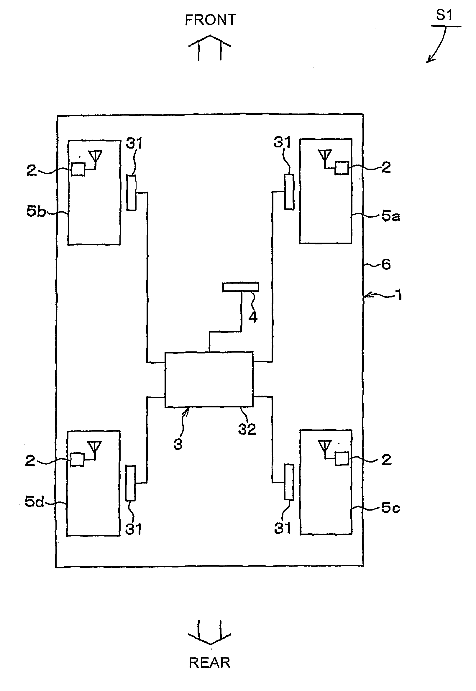
[0064]FIG. 1 shows the overall configuration of a tire inflation pressure sensing apparatus S1 according the first embodiment of the invention.

[0065] The tire inflation pressure sensing apparatus S1 is installed to a vehicle 1; it is configured to sense inflation pressures of four tires each of which is mounted on one of four wheels 5a-5d of the vehicle 1 (i.e., the front-right wheel 5a, the front-left wheel 5b, the rear-right wheel 5c, and the rear-left wheel 5d).

[0066] As shown in FIG. 1, the tire inflation pressure sensing apparatus S1 includes four transmitters 2, each of which is installed to one of the four wheels 5a-5d, a receiver 3 installed to the body 6 of the vehicle 1, and a warning device 4 electrically connected to the receiver 3.

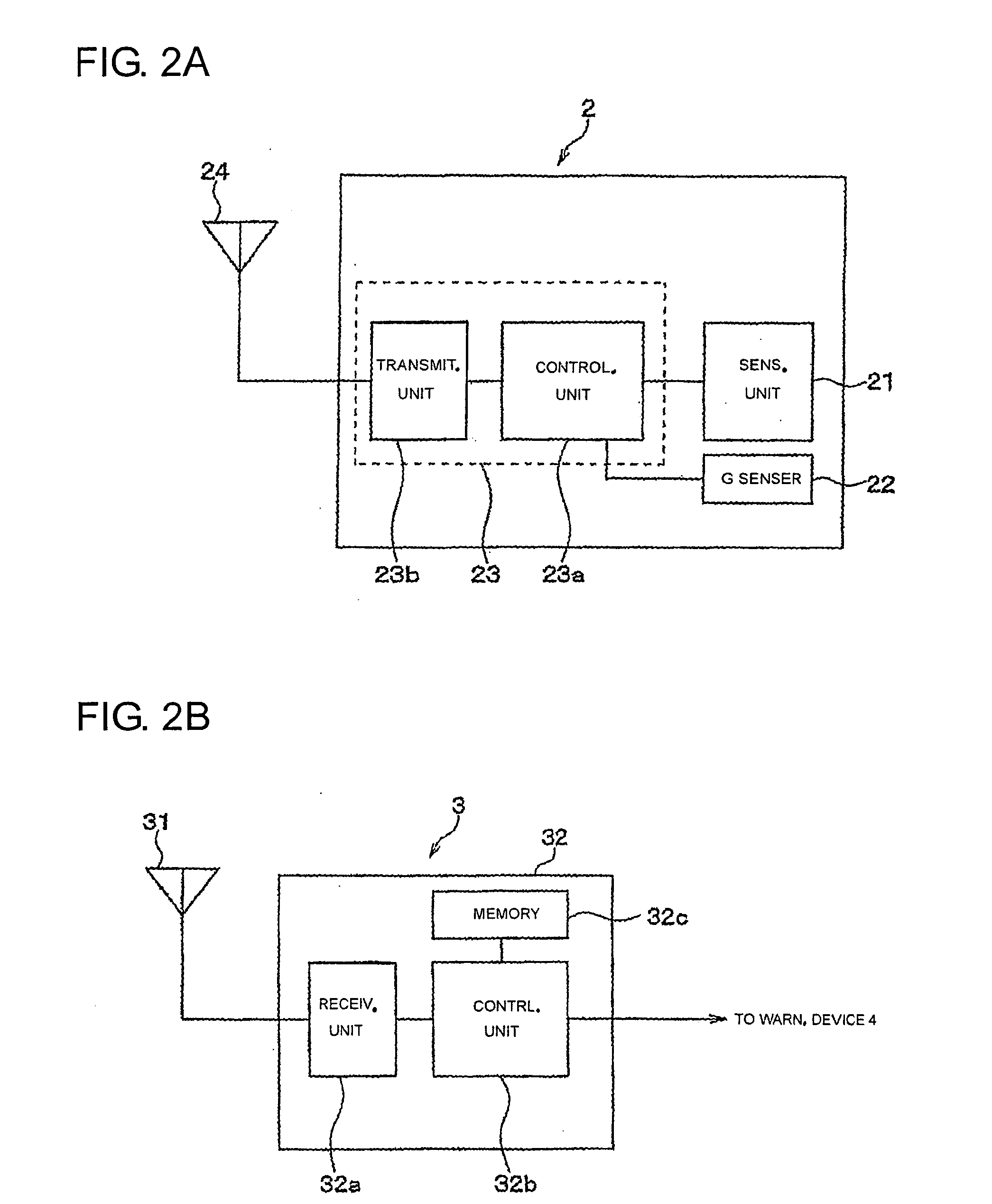
[0067] Each transmitter 2 is configured to sense an inflation pressure of a corresponding one of the four tires and transmit a frame that contains a signal representative of the sensed inflation pressure of the tire.

[0068] Referring to FIG...

second embodiment

[0124] In this embodiment, an inflation pressure sensing apparatus S2 is provided which has a structure almost identical to that of the inflation pressure sensing apparatus S1 according to the previous embodiment. Accordingly, only the difference in structure between the two tire inflation pressure sensing apparatuses is to be described below.

[0125] As described previously, in the tire inflation pressure sensing apparatus S1, each transmitter 2 includes the acceleration sensor 22 that is arranged on the wheel of the vehicle such that the sensing direction of the acceleration sensor 22 coincides with a radial direction of the wheel.

[0126] In comparison, in the tire inflation pressure sensing apparatus S2, the acceleration sensor 22 is so arranged, as shown in FIG. 7, on the wheel of the vehicle 1 that the sensing direction of the acceleration sensor 22 coincides with a circumferential direction of the wheel.

[0127] With the arrangement of acceleration sensor 22 shown in FIG. 7, the...

third embodiment

[0138] In this embodiment, a method of transmitting signals from a transmitter 2 of the tire inflation pressure sensing apparatus S1 or S2 to the receiver 3 of the same is provided, which is different from that described in the previous embodiments.

[0139] In the previous embodiments, the controlling unit 23a of the transmitter 2 stores in a frame signals representative of the inflation pressure of the tire and the temperature of air in the tire together with an ID signal. Then, the transmitting unit 23b of the transmitter 2 transmits the frame at once at a determined transmitting time.

[0140] However, according to the method of the present embodiment, the transmitter 2 stores the signals together with the ID signal in a frame that consists of a plurality of packets, and then the transmitting unit 23b transmits those packets separately at different determined transmitting times.

[0141] To illustrate the difference between the two transmitting methods, two frames that contain the sam...


PUM


Abstract

A tire inflation pressure sensing apparatus according to the present invention includes a transmitter and a receiver. The transmitter is provided on a wheel of a vehicle and includes a pressure sensor working to sense an inflation pressure of a tire on the wheel and an acceleration sensor working to generate a signal as a function of a component of gravitational acceleration in the sensing direction thereof. The transmitter is configured to determine a position thereof depending on the signal generated by the acceleration sensor and transmit the signal representative of the inflation pressure of the tire toward the receiver when a transmitting request is issued and the determined position thereof falls in a predetermined range. The receiver is provided on the body of the vehicle and is configured to receive the signal transmitted from the transmitter and determine the inflation pressure of the tire depending on the received signal.

Description

CROSS-REFERENCE TO RELATED APPLICATION [0001] This application claims priority from Japanese Patent Application No. 2004-138678, filed on May 7, 2004, the content of which is hereby incorporated by reference into this application. BACKGROUND OF THE INVENTION [0002] 1 Technical Field of the Invention [0003] The present invention relates generally to tire inflation pressure sensing apparatuses or sensors. More particularly, the invention relates to a direct-type tire inflation pressure sensing apparatus that includes a transmitter with a pressure sensor, which is installed to a wheel of a vehicle and configured to transmit a signal representative of an inflation pressure of a tire on the wheel sensed by the pressure sensor, a receiver installed to the body of the vehicle and configured to receive the signal transmitted from the transmitter, and an acceleration sensor employed to determine a position of the transmitter relative to the receiver so as to improve reliability of the sensin...

Claims


Application Information

Patent Timeline
IPC IPC(8): G01L17/00B60C23/00B60C23/04G08C17/02
CPCB60C23/0489B60C23/0416B60C23/0462
Inventor WATABE, NOBUYAOKUMURA, RYOZO
Owner DENSO CORP
Why Eureka
Try Eureka