Microscope optical system, microscope, and virtual slide forming system

Active Publication Date: 2005-11-10
NIKON CORP
View PDF10 Cites 47 Cited by
  • Summary
  • Abstract
  • Description
  • Claims
  • Application Information

AI Technical Summary

Benefits of technology

[0013] The present invention is made in view of the aforementioned problems and has an object to provide a technique capable of moving an observation

Problems solved by technology

Secondly, the mirror can be tilted with changing t

Method used


Image

  • Microscope optical system, microscope, and virtual slide forming system
  • Microscope optical system, microscope, and virtual slide forming system
  • Microscope optical system, microscope, and virtual slide forming system

Examples


first embodiment

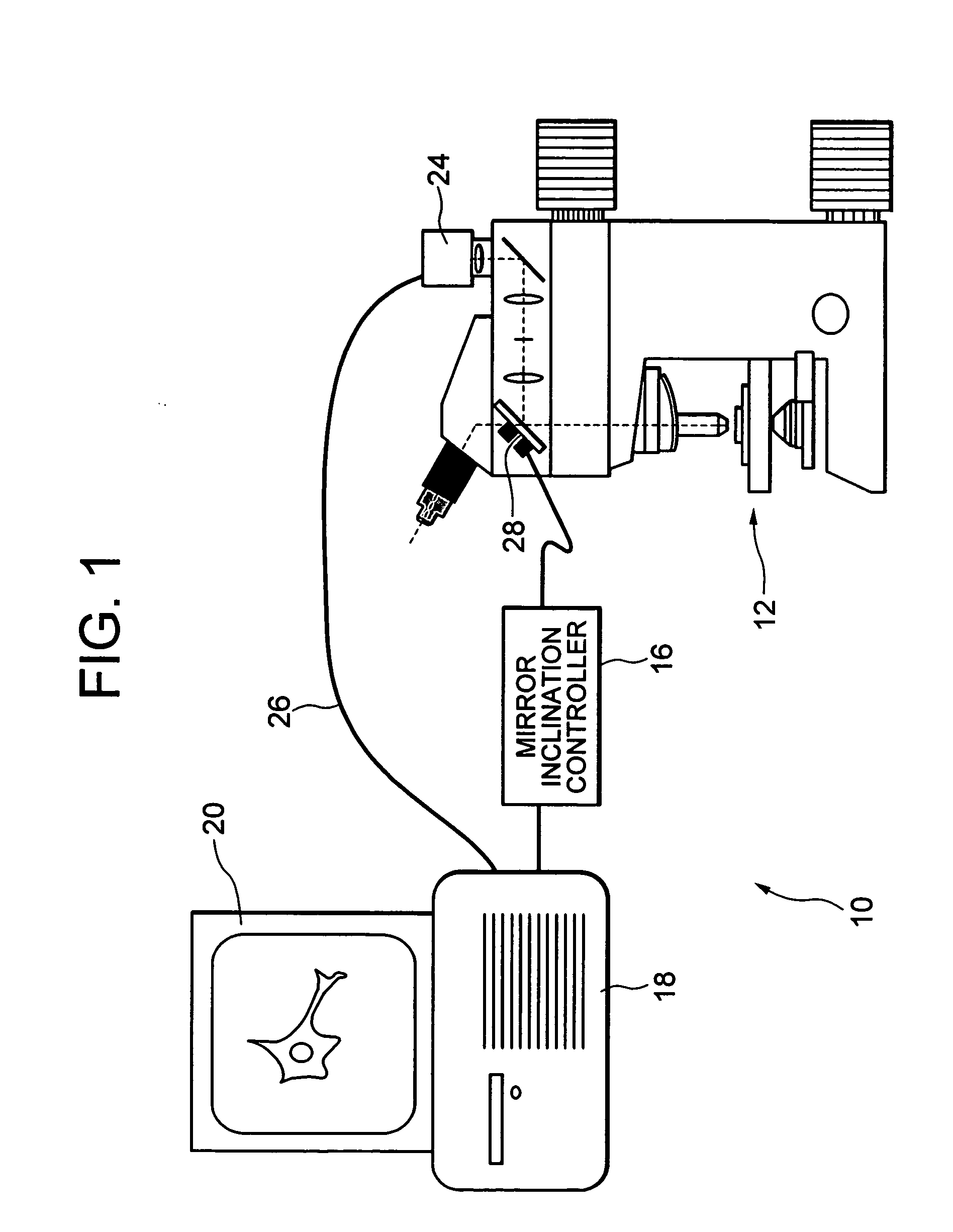
[0040]FIG. 1 is a schematic diagram showing a microscope system according to a first embodiment of the present invention. As shown in FIG. 1, the microscope system 10 has a microscope 12, a mirror inclination controller 16, a computer 18, and a monitor 20. The computer 18 obtains an image signal from a camera 24 of the microscope 12 through a cable 26 and displays an enlarged image of a sample on the monitor 20.

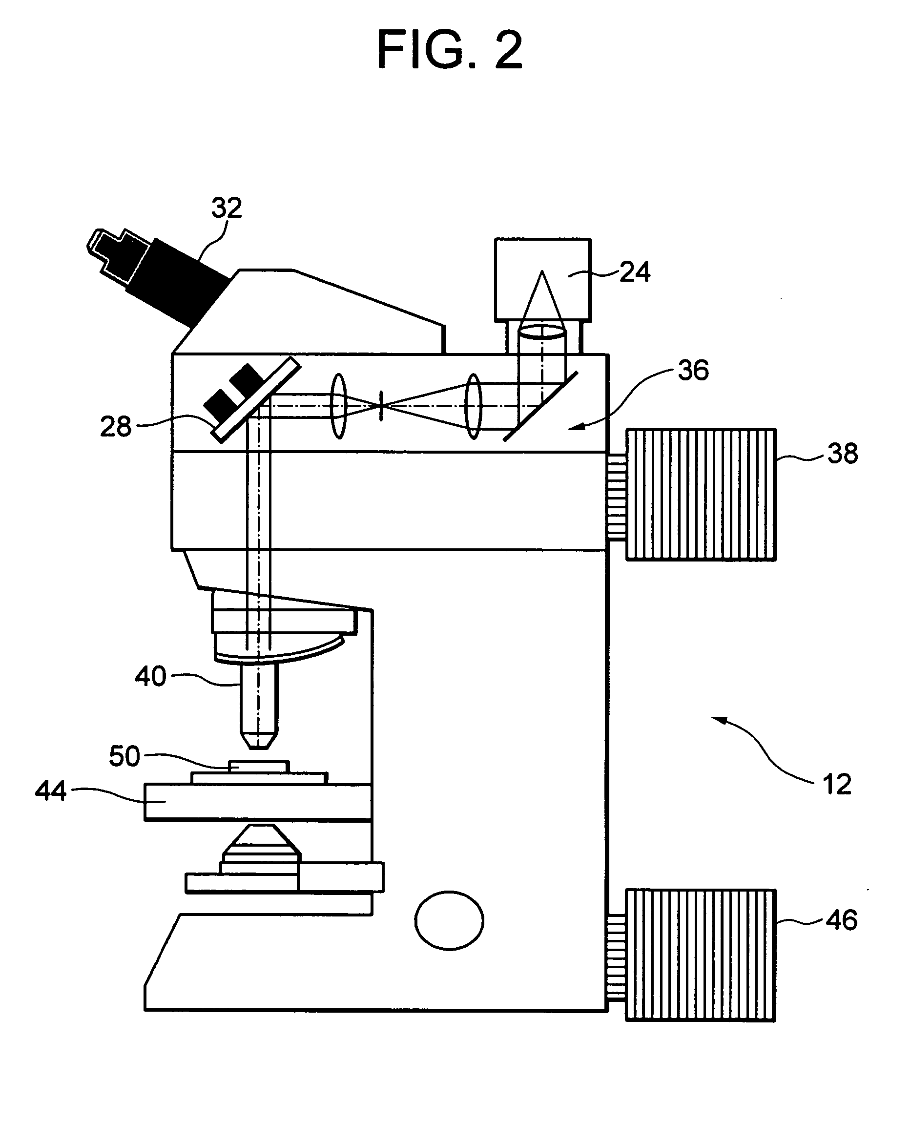
[0041]FIG. 2 is a schematic diagram showing the microscope 12 of FIG. 1 in detail. As shown in FIG. 2, the microscope 12 has a tilt mirror 28, an eyepiece portion 32, the camera 24, a variable magnification optical system 36, a fluorescence excitation light source 38, an objective lens 40, a stage 44, and a transmitted illumination light source 46.

[0042] The tilt mirror 28 is a semi-transparent mirror or a dichroic mirror. Accordingly, a bundle of light transmitting through the tilt mirror 28 is formed an observing image by an optical system (not shown because of publicly k...

second embodiment

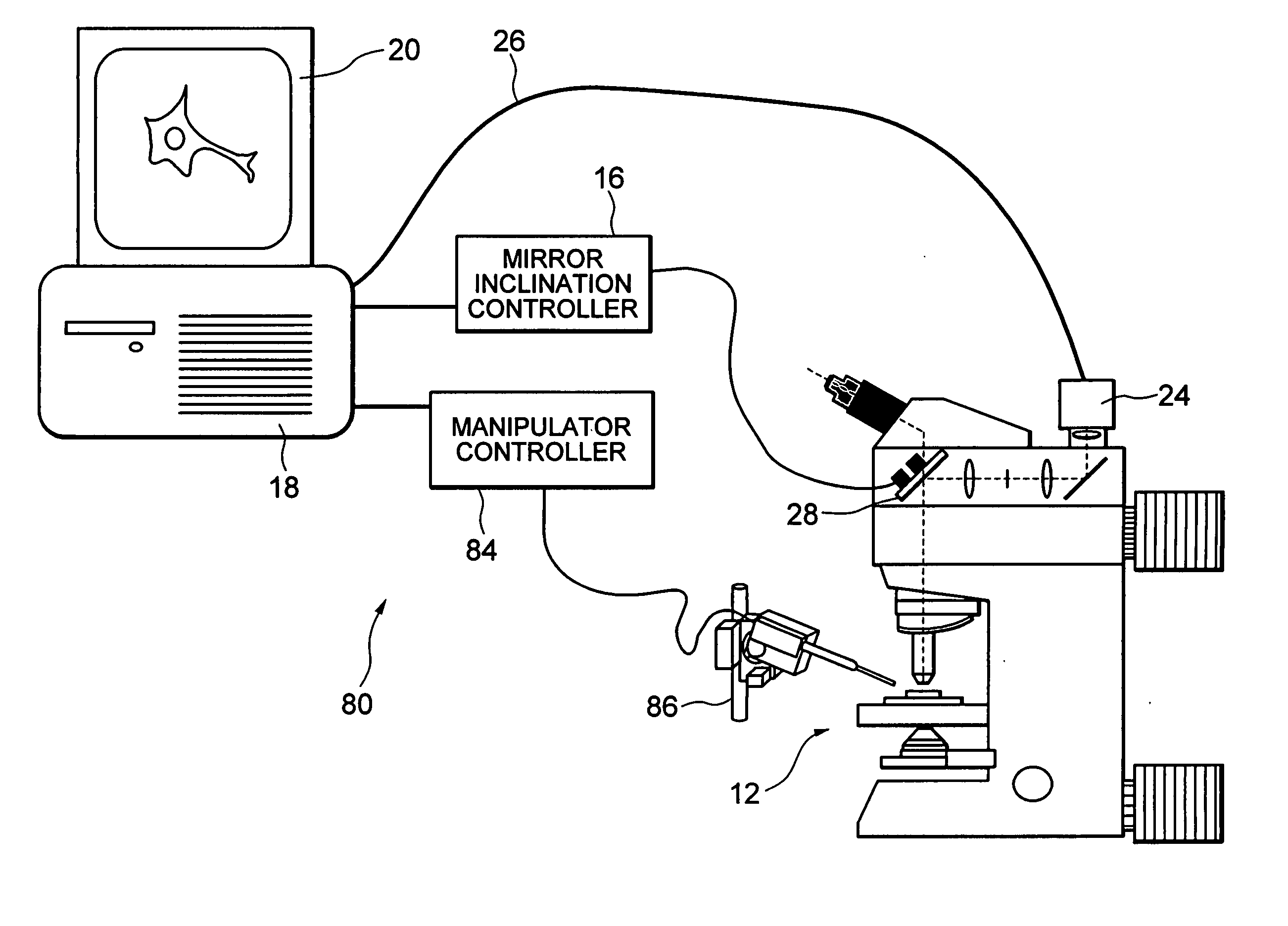
[0079]FIG. 6 is a schematic diagram showing a microscope system according to a second embodiment of the present invention. As shown in FIG. 6, a microscope system 80 according to the second embodiment includes a manipulator controller 84 and a micromanipulator 86 in addition to the elements of the microscope system 10 according to the first embodiment. The difference between the first embodiment and the second embodiment is that movement of the observation field of view is associated with movement of the micromanipulator 86 such that when the observation field of view is moved to the right, an electrode needle of the micromanipulator 86 is also moved to the right.

[0080] The difference between the second embodiment and the first embodiment is specifically explained below. For example, the instruction that the observation field of view is moved in association with the micromanipulator 86 is assumed to be input to the computer 18. In this case, when the instruction to move the observa...

third embodiment

[0083]FIG. 7 is a schematic diagram showing a microscope system according to a third embodiment of the present invention. As shown in FIG. 7, a microscope system 100 includes the monitor 20, the computer 18, the cable 26, a cable 108, the manipulator controller 84, the micromanipulator 86, and a microscope 110 according to the third embodiment.

[0084]FIG. 8 is a schematic diagram showing the microscope 110 of FIG. 7 in detail. As shown in FIG. 8, the microscope 110 includes the eyepiece portion 32, a fixed mirror 114, a fixed optical system 116, a moving optical system 120 (including the camera 24), the fluorescence excitation light source 38, the objective lens 40, the stage 44, and the transmitted illumination light source 46.

[0085] The difference between the third embodiment and the second embodiment is a mechanism for moving the observation field of view in the microscope 110. In the third embodiment, the observation field of view is moved by moving the moving optical system 12...


PUM


Abstract

The purpose is to move an observation field of view of a microscope without moving or changing an objective lens without varying position or state of a sample. A microscope optical system according to the present invention has a mirror that changes the direction of the optical path by reflection and locates in the optical path between an objective lens of the microscope and an image to be observed. The mirror is able to be tilted with changing the position of a reflecting surface of the mirror. Accordingly, the observation field of view is moved by tilting the mirror. In other words, the observation field of view can be moved without changing positional relation between the objective lens of the microscope and the sample.

Description

[0001] The disclosure of the following priority application is herein incorporated by reference: [0002] Japanese Patent Application No. 2004-140264 filed on May 10, 2004. BACKGROUND OF THE INVENTION [0003] 1. Field of the Invention [0004] The present invention relates to a microscope and an optical system thereof and a virtual slide forming system and in particular to a technique for moving an observing field of view in a microscope. [0005] 2. Related Background Art [0006] In ordinary microscope observation, after searching for a point to be observed with an objective lens having low magnification, the point is observed with enlarging by an objective lens having high magnification. However, there is a possibility of danger that a position of a sample is slipped out by an impact upon changing an objective lens. [0007] In an example disclosed in Japanese Patent Application Laid-Open No. 2002-31758, in order to observe a wide area, the magnification of the objective lens is limited to ...

Claims


Application Information

Patent Timeline
IPC IPC(8): G02B21/00G02B21/36
CPCG02B21/32G02B21/002
Inventor SASE, ICHIROWATANABE, KATSUYA
Owner NIKON CORP
Why Eureka
Try Eureka