Electronic clock

Inactive Publication Date: 2005-11-10
CITIZEN WATCH CO LTD
View PDF4 Cites 0 Cited by
  • Summary
  • Abstract
  • Description
  • Claims
  • Application Information

AI Technical Summary

Benefits of technology

[0018] In an electronic timepiece driven by electric energy generated by a power generating unit, the electric timepiece includes a storage unit connected with the power generating unit in parallel through an electronic switch, a control unit that controls the electronic switch, a power generation detecting unit that detects a power generation state of the power generating unit, an informing unit that informs a detection result of the power generation detecting unit to the outside, and an external operating member. In this case, the external operating member is operated so that the power generation detecting unit can go into action while a power generation detecting operation is performed under a condition that the electronic switch is turned off by the control unit and the result is informed to the outside through the informing unit. Thus, an electronic timepiece can be provided which can check an operation of the power generating unit securely irrespective of the state of the storage unit. Furthermore, whether the power generation state of the power generating unit at a predetermined power generation state satisfies a desired value or not can be examined simply and with stability.
[0020] Furthermore, in an electronic timepiece driven by electric energy generated by a power generating unit, the electric timepiece includes a first storage unit connected with the power generating unit in parallel, a second storage unit connected with the power generating unit in parallel through an electronic switch, a control unit that controls the electronic switch, a power generation detecting unit that detects a power generation state of the power generating unit, an informing unit that informs a detection result of the power generation detecting unit to the outside, and an external operating member. In this case, the external operating member is operated so that the power generation detecting unit can go into action while a power generation detecting operation is performed under a condition that the electronic switch is turned off by the control unit and the result is informed to the outside through the informing unit. Thus, even after the electronic switch is turned OFF, the voltage detecting unit can operate by using charges stored in the first storage unit, and stable detection of power generation can be performed thereby.
[0022] Furthermore, the power generation detecting unit detects a power generation state of the power generating unit by detecting voltage of the first storage unit. Thus, voltage of the voltage detecting unit can be detected by using charges stored in the first storage unit, and stable detection of power generation can be performed thereby.

Problems solved by technology

However, in a process for manufacturing an electronic timepiece, the examinations under those states increase the number of man-hours and / or increase the manufacturing costs.
In this way, for checking operations of the power generating unit 50, the conventional technology has problems that sufficient examinations cannot be performed or that a large amount of efforts is required for performing sufficient examinations.

Method used


Image

  • Electronic clock
  • Electronic clock
  • Electronic clock

Examples


first embodiment

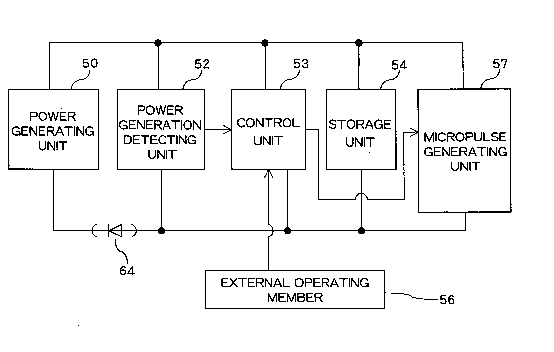
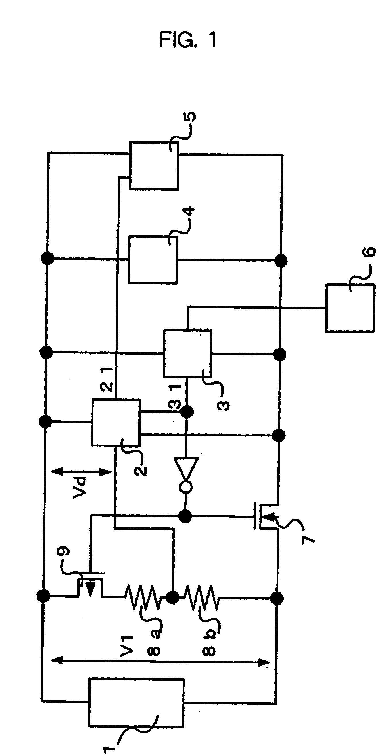
[0034] According to the above-described first embodiment, since the control unit 3 and power generation detecting unit 2 are driven by voltage supplied from the storage unit 4, the power generation voltage V1 generated by the power generating unit 1 is divided by the resistor 8a and resistor 8b in order to detect voltage equal to or larger than voltage output from the storage unit 4. In other words, in the first example of the construction in FIG. 1, while the power generating unit 1 outputs V1, the power generation detecting unit 2 and control unit 3 operate at voltage (V4, for example) output by the storage unit 4.

[0035] If V1≦V4, the power generation detecting unit 2 that measures V1 operates at voltage V4 higher than V1 and can therefore measure V1 directly.

[0036] However, if V1>V4 (highly possible in the invention having the power generating unit 1 and the storage unit 4 separately), the power generation detecting unit 2 that is driven by V4 cannot directly measure V1 that is ...

second embodiment

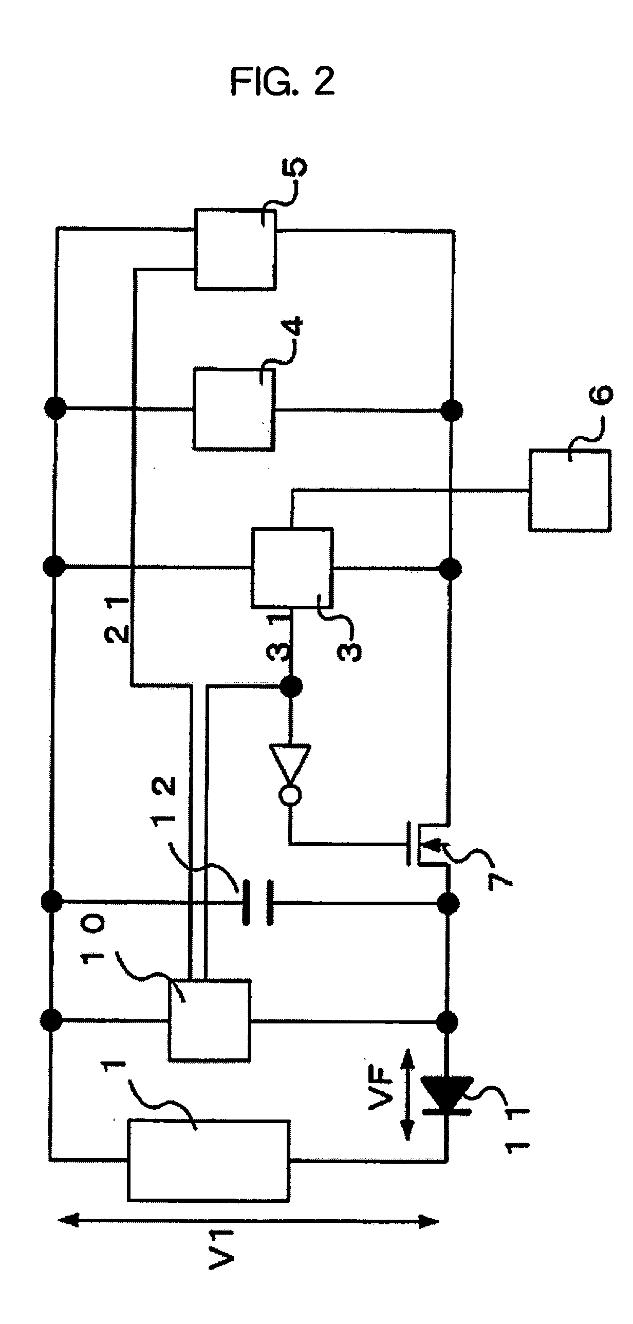
[0046] The first resistor 8a, second resistor 8b and p-channel transistor 9 shown in the first example are not described and are omitted in the second example since a potential equal to or larger than power supply voltage of the power generation detecting unit 10 does not have to be detected because the power supply potential of the voltage detecting unit 10 varies in accordance with the potential output from the power generating unit 1 in the In other words, since the voltage detecting unit 10 is driven by voltage (V1+VF) of the capacitor 12 to be detected thereby in the second example having the construction in FIG. 2, the detection can be performed without resistance division.

[0047] As described above, according to the first and second examples, in an electronic timepiece including a power generating unit and being operated by electric energy generated by the power generating unit, whether a power generation state from the power generating unit at a predetermined power generatio...


PUM


Abstract

In detecting power generation of an electronic timepiece having a conventional power generating unit, voltage output by the power generating unit is limited by output from a storage unit since the power generating unit and the storage means are connected when the power generation state is detected, and voltage equal to or larger than voltage output from the storage unit cannot be detected. An electronic timepiece is provided which can overcome the problem and can check an operation of the power generating unit securely irrespective of the state of the storage means. In an electronic timepiece driven by power stored from a power generating unit (1) into a storage unit (4), the electronic timepiece includes a power generation detecting unit (2) that detects a power generation state of the power generating unit (1) and a switch unit (7) that separates the power generating unit (1) and the storage unit (4) when the power generation state of the power generating unit (1) is detected. In this case, the switch (7) between the power generating unit (1) and the storage unit (4) is controlled to OFF so that the output from the power generating unit (1) cannot be limited by the output from the storage unit (4).

Description

TECHNICAL FIELD [0001] The invention relates to an electronic timepiece having a power generating unit and being driven by power generated by the power generating unit, and, more specifically, it relates to a technology for detecting a power generation state of the power-generating unit and informing the detection result. BACKGROUND ART [0002] In recent years, electronic timepieces each of which includes a power generating unit for saving efforts of battery changes required in conventional electronic timepieces to enhance the convenience of users and which is driven by power generated by the power generating unit have been developed and commercially available. [0003] In an electronic timepiece including a power generating unit, whether the power generating unit is normally operating or not, whether a path for feeding power generated by the power generating unit to the electronic timepiece is securely connected or not, and so on must be checked in production steps in order to secure ...

Claims


Application Information

Patent Timeline
IPC IPC(8): G04C10/00G04G19/00G04C10/04
CPCG04C10/04G04C10/00
Inventor HIGUCHI, HARUHIKOMURAKAMI, AKIYOSHIFUNAHASHI, MOTOKI
Owner CITIZEN WATCH CO LTD
Why Eureka
Try Eureka