Focusing position detection method, focusing position detector, recording medium, and focusing position detection program

Active Publication Date: 2021-08-12
SCREEN HLDG CO LTD
View PDF0 Cites 1 Cited by
  • Summary
  • Abstract
  • Description
  • Claims
  • Application Information

AI Technical Summary

Benefits of technology

The present invention allows for stable detection of a focusing position even when multiple object images are relatively dark or include high-luminance regions. The invention can be adapted to include or exclude certain components and can be combined with other innovations to create a more complex and customized version of the invention. The technical effects of the invention include improved accuracy and efficiency in focus detection, regardless of the image quality or brightness.

Problems solved by technology

Herein, under the condition that the luminance of the imaging object image is extremely low, it was difficult to accurately detect the focusing position even by using the above-described conventional technique.
For this reason, the difference between the luminance of the imaging object image and noise is small and the object image becomes vulnerable to background noise.
Then, in the image including the high-luminance region (see the rows (a) and (b) of FIG. 7 described later), it may be possible to detect the focused focal point position after excluding the high-luminance region, but this method cannot sufficiently remove the effect of the dead cell or the like.
In other words, the difference between the luminance of the imaging object image and noise becomes large.
Since the imaging objects are the cells, however, the repeat of imaging causes problems relating to the cells (phototoxicity, fluorescence photobleaching) and a problem of imaging latency time.

Method used


Image

  • Focusing position detection method, focusing position detector, recording medium, and focusing position detection program
  • Focusing position detection method, focusing position detector, recording medium, and focusing position detection program
  • Focusing position detection method, focusing position detector, recording medium, and focusing position detection program

Examples


embodiment b

The Embodiment B

[0051]Next, with reference to FIGS. 5 to 11, the embodiment B will be described. Hereinafter, as the embodiment B, four embodiments (the second to fifth embodiments) will be described, and constituent elements identical to those in the embodiment A are represented by the same or corresponding reference signs and description thereof will be omitted.

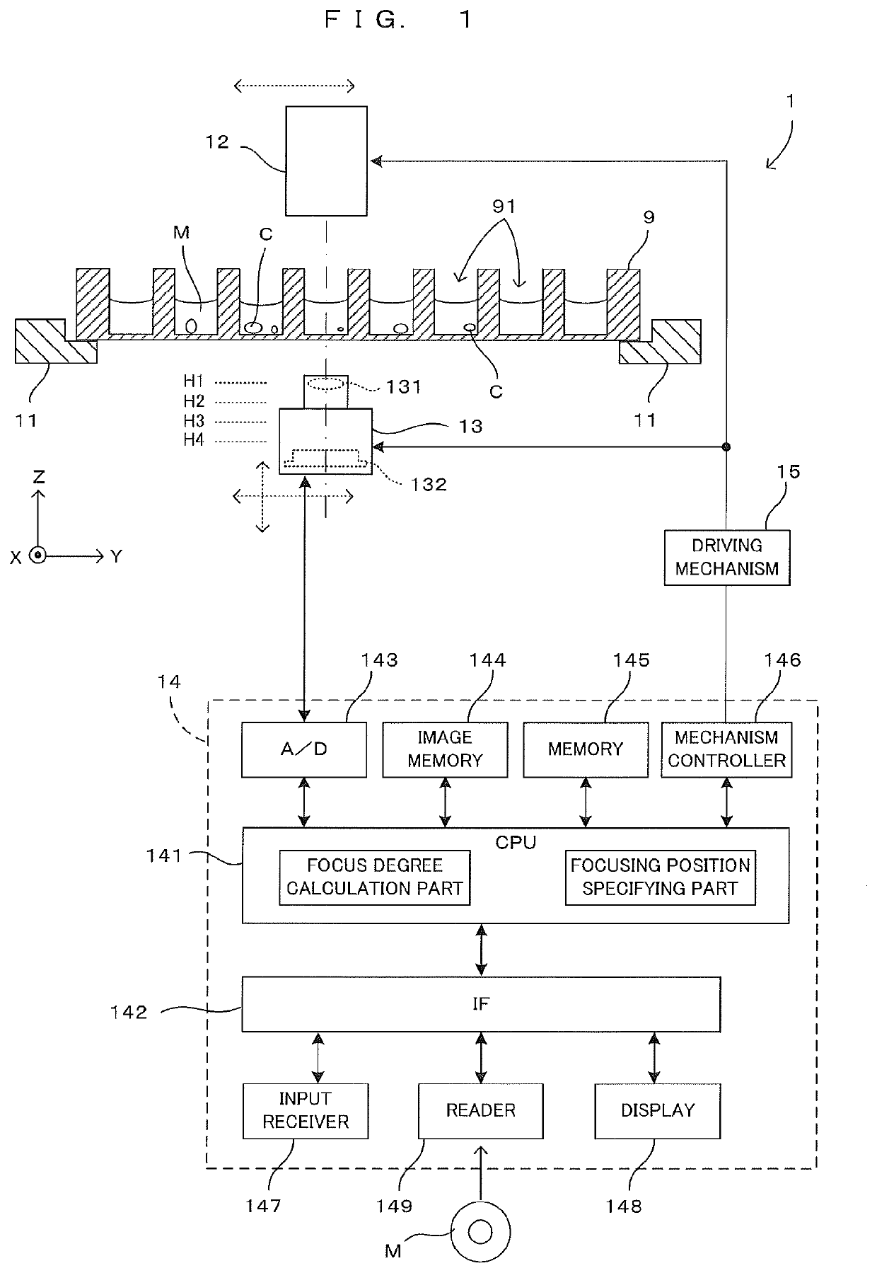
[0052]FIG. 5 is a diagram showing a schematic configuration of an imaging apparatus equipped with the second embodiment of the focusing position detector in accordance with the present invention. The second embodiment is largely different from the first embodiment (the embodiment A) in that the CPU 141 has a saturation region acquisition part and part of the process performed by the CPU 141 is changed. Specifically, the CPU 141 executes a control program stored in the memory 145 to perform a saturation region acquisition process, a focus degree calculation process, a focusing position specifying process, and the like which ...


PUM


Abstract

In a focusing position detection method, a second step is carried out. The second step includes dividing the object image into a plurality of local regions, obtaining a local value indicating the degree of focalization from the local region for each of the plurality of local regions and obtaining the focus degree on the basis of the plurality of local values. Thus, even when a plurality of object images acquired by imaging an imaging object by using an imager while changing a focal position along an optical axis are relatively dark or include a high-luminance region, it is possible to stably detect a focusing position without repeating detection operations.

Description

CROSS REFERENCE TO RELATED APPLICATIONS[0001]Contents disclosed in the specification, drawings and claims of the following Japanese Patent Applications are all incorporated herein by reference:[0002]Japanese Patent Application No. 2020-031528 (filed on Feb. 27, 2020); and[0003]Japanese Patent Application No. 2020-031529 (filed on Feb. 27, 2020).BACKGROUND OF THE INVENTION1. Field of the Invention[0004]The present invention relates to a focusing position detection technology for detecting a focusing position on the basis of a plurality of object images acquired by imaging an imaging object by using an imager while changing a focal position along an optical axis.2. Description of the Related Art[0005]In some cases, for culture and analysis of cells, used are images obtained by imaging a specimen containing the cells. The specimen is prepared by using a flat plate-like container provided with a plurality of wells (recesses), which is referred to as a well plate, a microplate, or the li...

Claims


Application Information

Patent Timeline
IPC IPC(8): H04N5/232
CPCH04N5/232127H04N17/002H04N23/675G06T2207/10148G06T7/70G06T2207/30072G01N21/6458G02B21/36G02B7/28G02B7/36G03B13/36G03B15/02G01N2021/646
Inventor YASUDA, TAKUYA
Owner SCREEN HLDG CO LTD
Why Eureka
Try Eureka