Image coding apparatus and image decoding apparatus and their control methods, and computer program and computer-readable storage medium

a technology of image data and coding apparatus, applied in the field of image data coding and decoding technique, can solve the problems of code amount, memory capacity increase, and the above method is not frequently used, and achieve the effect of easy and efficient encoding of image data

Inactive Publication Date: 2005-11-10
CANON KK
View PDF30 Cites 52 Cited by
  • Summary
  • Abstract
  • Description
  • Claims
  • Application Information

AI Technical Summary

Benefits of technology

[0015] The present invention has been made in consideration of the above problems, and provides a technique for easily and efficiently encoding i

Problems solved by technology

However, the above method is not frequently employed for various reasons such as the complexity of processing, the increment in memory capacit

Method used


Image

  • Image coding apparatus and image decoding apparatus and their control methods, and computer program and computer-readable storage medium
  • Image coding apparatus and image decoding apparatus and their control methods, and computer program and computer-readable storage medium
  • Image coding apparatus and image decoding apparatus and their control methods, and computer program and computer-readable storage medium

Examples


first embodiment

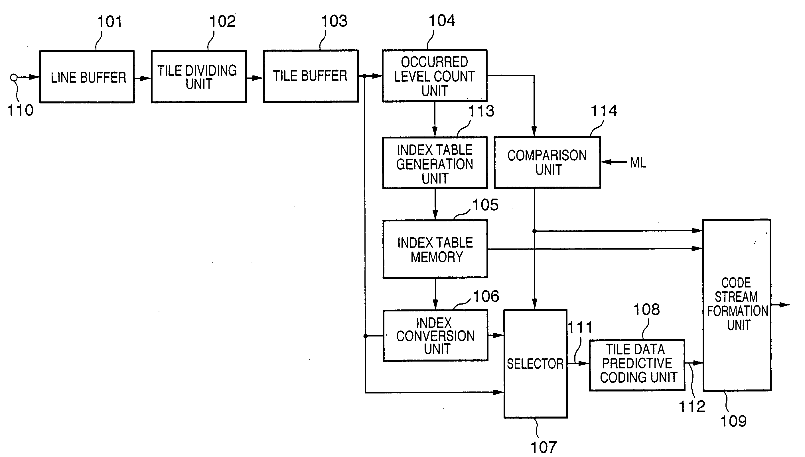
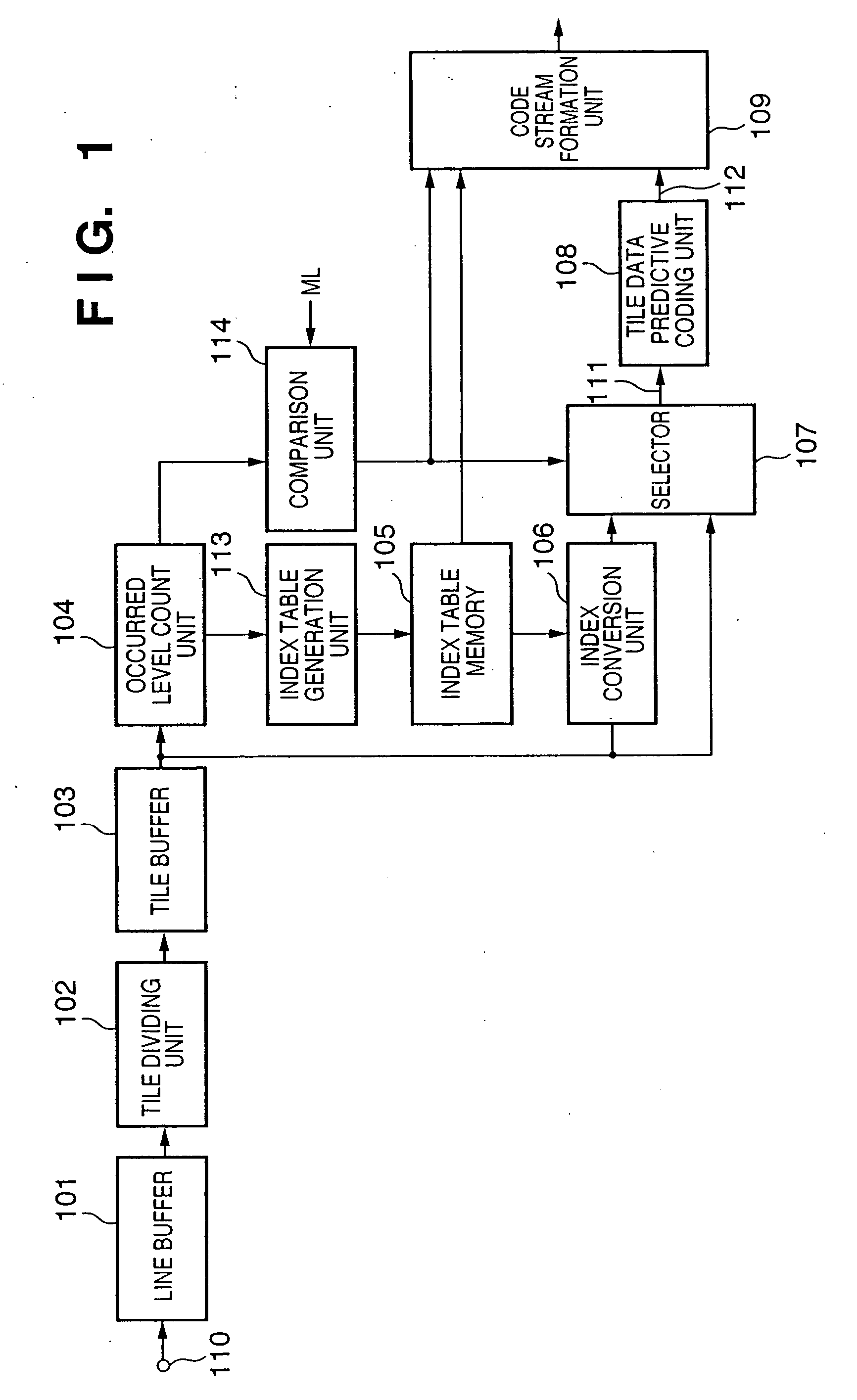
[0042]FIG. 1 is a block diagram showing the construction of an image processing apparatus (image coding apparatus) according to a first embodiment of the present invention.

[0043] In FIG. 1, reference numeral 110 denotes an input terminal to input image data. In the present embodiment, pixel data having respectively 8-bit (256 gray levels) R, G and B component brightness values is inputted by 1 line. The input image data is not limited to RGB color space data but data in other color space such as YMC, Lab or YCbCr may be inputted. Since it is well known for the persons skilled in the art that in the case of YMC space, each pixel is represented by YMC density values, those skilled art will easily understand the input data is not limited to the brightness values.

[0044] Numeral 101 denotes a line buffer which holds plural line color images. In the present embodiment, the number of lines stored in the line buffer 101 is Th. As 1 pixel corresponds to RGB three components and each compon...

second embodiment

[0154] In the first embodiment and the modification, the degree of discrete distribution (sparseness) of respective color-component brightness values occurred in 1 tile is represented by the respective color-component number of occurred levels NLV(R), NLV(G) and NLV(B). That is, when the number of brightness types occurred in a limited brightness range (0 to 255 as 8-bit data) is small, there is a high probability that the brightness distribution is discrete to the brightness axis, in other words, sparse. However, the relation “number of occurred levels is small=degree of discrete distribution is high” does not necessarily hold.

[0155]FIGS. 16A and 16B are histograms showing brightness on the horizontal axis and occurrence frequency on the vertical axis in a case where the number of occurred levels NLV( )=8 holds. FIG. 16A shows an example where the occurred brightness values are appropriately discrete, and FIG. 16B, an example where the occurred brightness values are clustered to t...

third embodiment

[0168] In the first embodiment, the modification and the second embodiment, all the tiles are subjected to lossless coding. However, the present invention is not limited to this coding but applicable to a combination of lossless coding and lossy coding for the sake of improvement of compressibility. As a third embodiment, an example of image processing apparatus which encodes tile data by lossless and lossy coding methods, and selects one of the coded results with smaller code amount, as tile coded data, will be described. In a case where a code amount, as a result of best possible high-quality coding using lossy coding mainly for natural image such as JPEG method recommended as an international standard coding method, is compared with a code amount as a result of lossless coding based on predictive coding, the code amount by the lossless coding is smaller in the case of artificially generated character / line art image and CG image, while the code amount by the lossy coding is smalle...


PUM


Abstract

An image coding apparatus for efficient coding on image data having discrete pixel values such as a CG image or a limited color image as well as a natural image where pixel value changes are mild. For this purpose, a tile dividing unit divides multi-valued image data into tiles. An occurred level count unit outputs the result of counting of the number of brightness values in the tile to a comparison unit and outputs the existing brightness values to an index table generation unit. The index table generation unit allocates continuous index values to the existing brightness values, and stores the result of allocation into an index memory table. An index conversion unit replaces the input pixel values in the tile with index values, and outputs the index values to a selector. The selector selects one of the brightness values in the tile or the index values based on the result of comparison by the comparison unit, and outputs the selected values to a tile data predictive coding unit so as to perform predictive coding processing.

Description

FIELD OF THE INVENTION [0001] The present invention relates to an image data coding and decoding technique. BACKGROUND OF THE INVENTION [0002] Conventionally, an image processing apparatus based on predictive coding is known. The predictive coding is realized with a sequence conversion unit to convert image data to prediction errors by predictive conversion, and an entropy coding unit to convert the prediction errors outputted from the sequence conversion unit to coded data with reduced redundancy by entropy coding such as Huffman coding. [0003] As the characteristic of prediction-error occurrence frequency differs in accordance with the image, it is desirable to improve coding efficiency in order to perform optimum entropy coding on each image. [0004] As a method for realizing optimum entropy coding on each image, 2-pass coding processing is known. In this method, the characteristic of prediction-error occurrence frequency is examined in the first pass, then an entropy coding metho...

Claims


Application Information

Patent Timeline
IPC IPC(8): H03M7/36H04N1/413H04N1/417H04N7/12H04N19/103H04N19/137H04N19/167H04N19/194H04N19/50H04N19/61H04N19/625H04N19/63H04N19/91H04N19/93
CPCH04N19/13H04N19/39H04N19/15
Inventor KAJIWARA, HIROSHIMATSUMOTO, YUKI
Owner CANON KK
Why Eureka
Try Eureka