Electrical terminal block

a terminal block and terminal technology, applied in the direction of electrical connections, electrical apparatus, electrical connection structural associations, etc., can solve the problems of high (and often potentially fatal) electrical shock, high electrical shock risk, and high electrical shock risk of electricians (or other suitable personnel) who frequently access the terminal block, so as to facilitate and safely conduct coupling and prevent electrical shock

Active Publication Date: 2005-11-10
CONCENTRIC DEVICES INC
View PDF23 Cites 44 Cited by
  • Summary
  • Abstract
  • Description
  • Claims
  • Application Information

AI Technical Summary

Benefits of technology

[0014] It is another object of the present invention to provide a terminal block as described above which is designed to enable each electrical wire to be easily and safely ...

Problems solved by technology

As a result, a considerable amount of electrical current often continuously passes through the bus bars of the terminal block.
Accordingly, it has been found that electricians (or other suitable personnel) who frequently access the terminal block are susceptible to high (and often potentially fatal) levels of electrical shock because the terminal block is equipped with no means for temporarily shunting electrical charge present in the bus bars, which is highly undesirable.
As a result, the top surface of each bus bar is rendered highly susceptible to inadvertent contact by any individual who works in the vicinity of the terminal block.
As noted above, because each bus bar serves as a conductive path between a pair of wires, inadvertent contact with a bus bar can result in serious physical injury or death, which is highly undesirable.
As a third drawback, terminal blocks of the type described above are often provided with a plurality of ring lug receiving terminals, each terminal being designed so as to require a relatively time consuming and labor intensive process for connecting the ring lug of a wire thereto.
As can be appreciated, thi...

Method used


Image

  • Electrical terminal block
  • Electrical terminal block
  • Electrical terminal block

Examples


Embodiment Construction

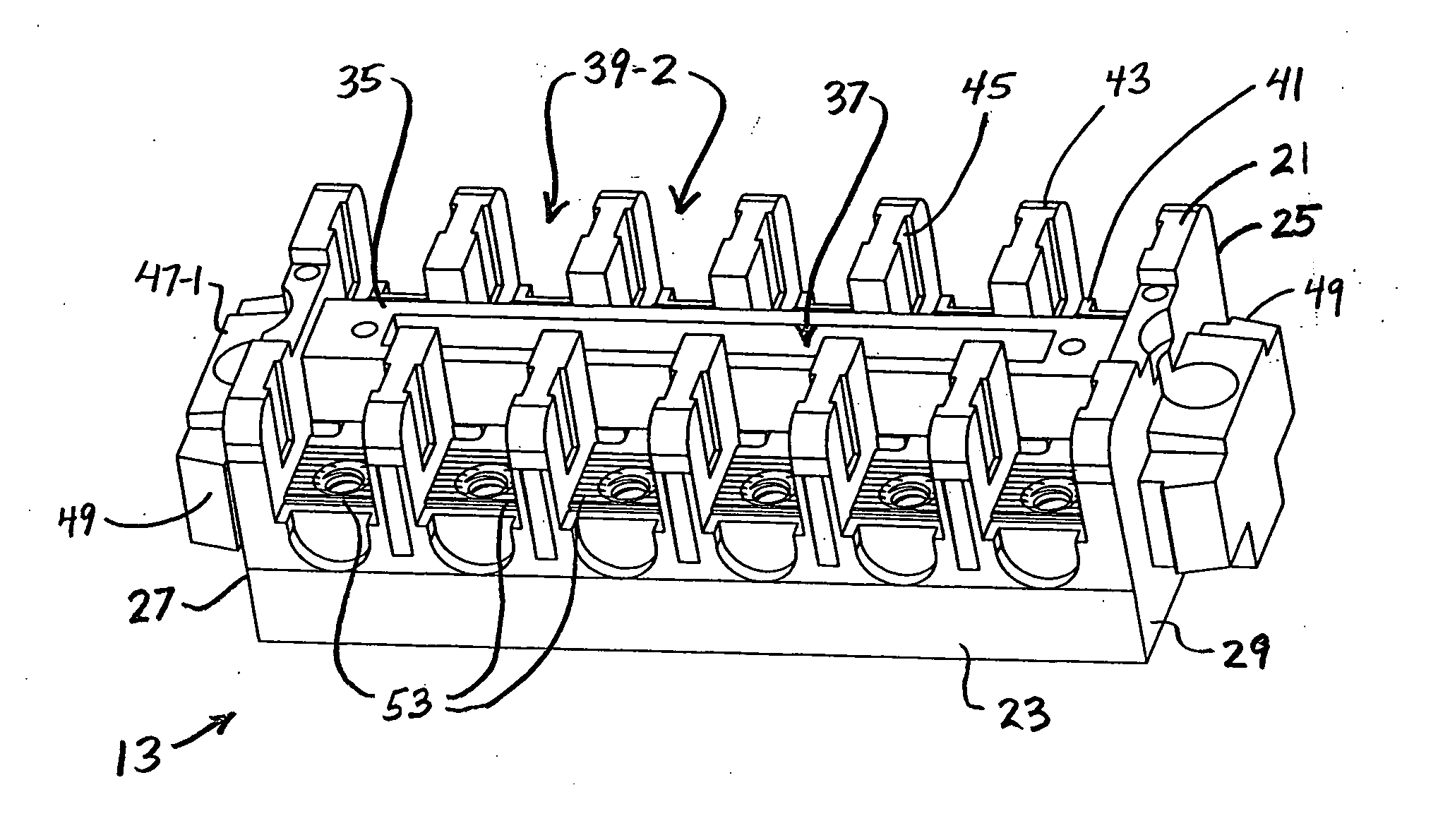
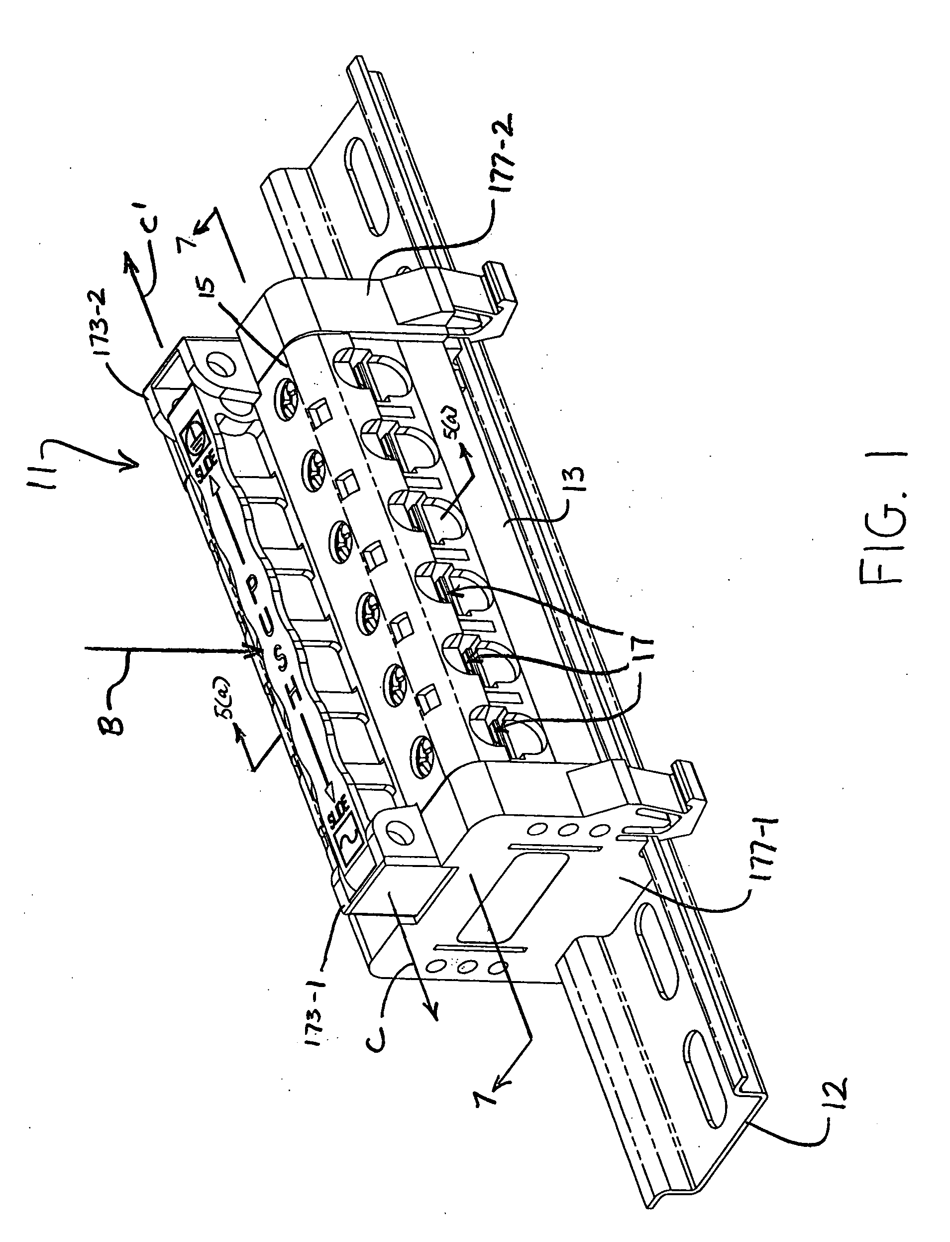
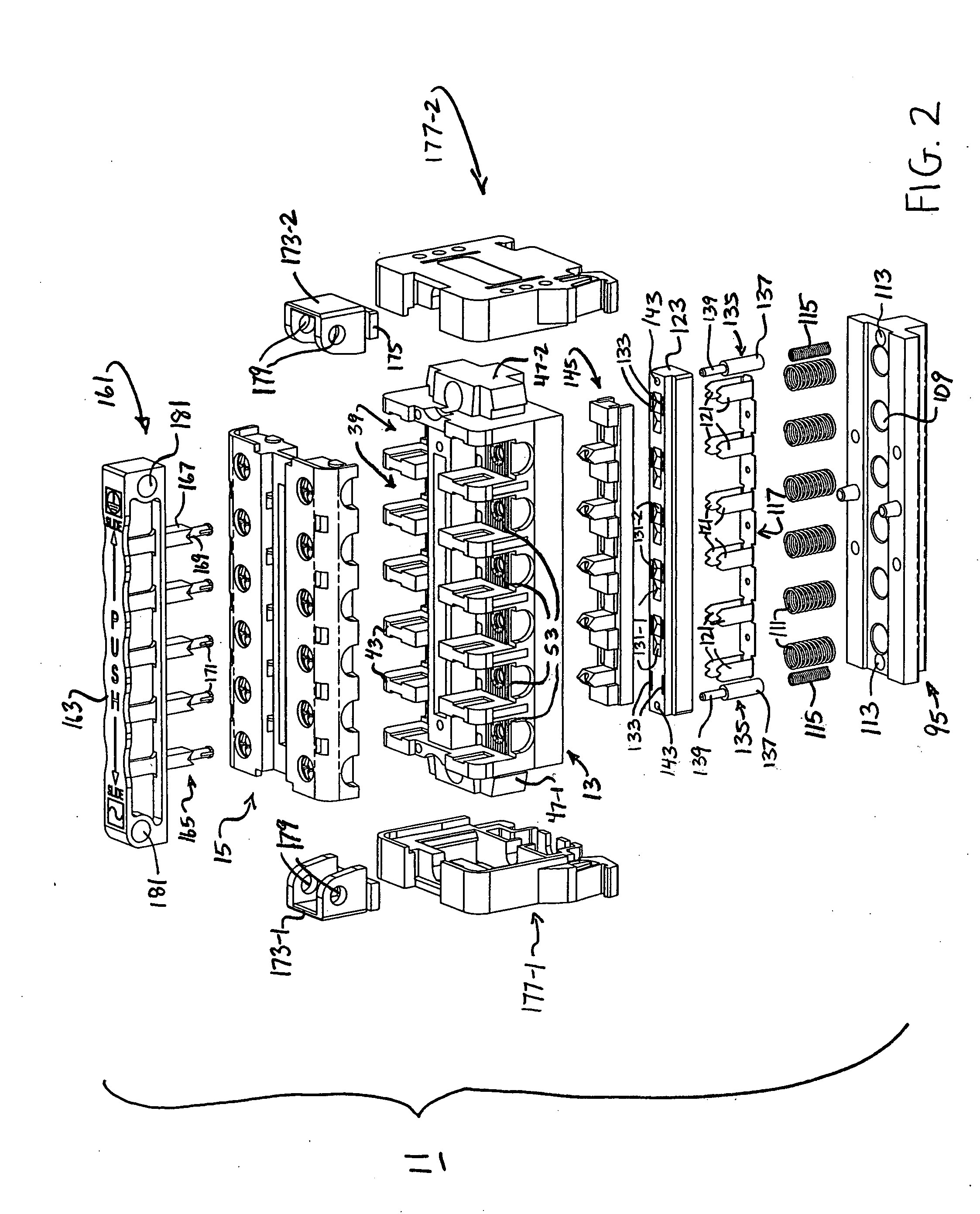
[0041] Referring now to FIGS. 1-3, there is shown an electrical terminal block (also referred to herein simply as a terminal block) constructed according to the teachings of the present invention, the terminal block being represented generally by reference numeral 11. As will be described further below, terminal block 11 can be used to electrically connect at least one pair of wires. In addition, terminal block 11 is adapted to be mounted onto a conventional DIN rail 12, as seen most clearly in FIG. 1.

[0042] Terminal block 11 includes a base 13 and a cover assembly 15 adapted to be removably mounted onto base 13 by means of a forced snap fit. Together, base 13 and cover assembly 15 define six pairs of wire receiving receptacles 17, each pair of receptacles 17 being conductively coupled together, as will be described further below. However, it should be noted that terminal block 11 is not limited to a particular number of pairs of receptacles 17. Rather, it is to be understood that ...


PUM


Abstract

A terminal block for conductively coupling multiple pairs of electrical wires includes a deadfront cover mounted onto a non-conductive base so as to define multiple pairs of wire receiving receptacles, each pair of wire receiving receptacles being electrically connected together via a conductive bus bar. As one feature of the present invention, a conductive shunt can be disposed by means of a manually operable shunt switch to selectively contact all of the bus bars in order to discharge any current present thereon. As another feature of the present invention, a plurality of finger-safe captive screw assemblies are retained within the cover, each captive screw assembly including a screw which can be driven into a threaded bore formed in one end of a corresponding bus bar. As yet another feature of the present invention, multiple pairs of interchangeable end caps can be removably snap-fit mounted on the base to enable the terminal block to be retained onto a wide variety of different surfaces. As yet still another feature of the present invention, a DIN rail lock is retained between each end cap and the base and includes one or more sharpened teeth which can be driven into the surface of the DIN rail to lock the terminal block in place.

Description

BACKGROUND OF THE INVENTION [0001] The present invention relates generally to electrical connectors and more particularly to electrical terminal blocks for connecting wire pairs. [0002] Electrical terminal blocks (also commonly referred to as terminal junction blocks, junction blocks, or barrier blocks) are well known and widely used in commerce as devices for safely, conveniently and efficiently connecting together one or more pairs of wires or cables. For example, electrical terminal blocks are commonly used in the telecommunications industry to provide convenient and compact means for connecting telephone customer service wires (i.e., the “service” side) to telephone exchange distribution cables (i.e., the “exchange” side). Specifically, an electrical terminal block used in the telecommunications industry typically includes a plurality (e.g., 4, 6, 8, 10, 12, 24, etc.) of interconnected terminal pairs which can be used to connect each individual distribution cable wire on the exc...

Claims


Application Information

Patent Timeline
IPC IPC(8): H01R9/22H01R9/26
CPCH01R9/2641
Inventor JOHANSEN, ARNOLD W.KIMBALL, PHILLIPNELSON, DAVID CHARLES
Owner CONCENTRIC DEVICES INC
Why Eureka
Try Eureka