
Vertebral interbody spacer

a technology of interbody spacer and vertebrae, which is applied in the field of interbody, can solve the problems of inconvenient removal, inconvenient fusion of vertebrae, and often too closely spaced vertebrae anteriorly, so as to facilitate the packing of bone chips, promote the desired curvature of the spine, and promote the effect of fusion between the vertebra

Active Publication Date: 2005-11-10
WARSAW ORTHOPEDIC INC
View PDF40 Cites 168 Cited by
  • Summary
  • Abstract
  • Description
  • Claims
  • Application Information

AI Technical Summary

Benefits of technology

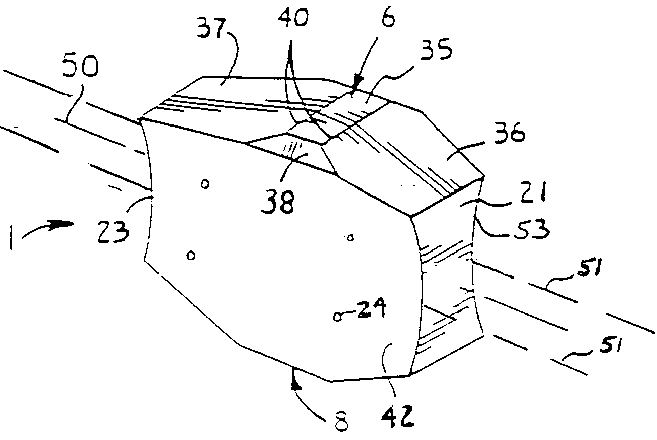
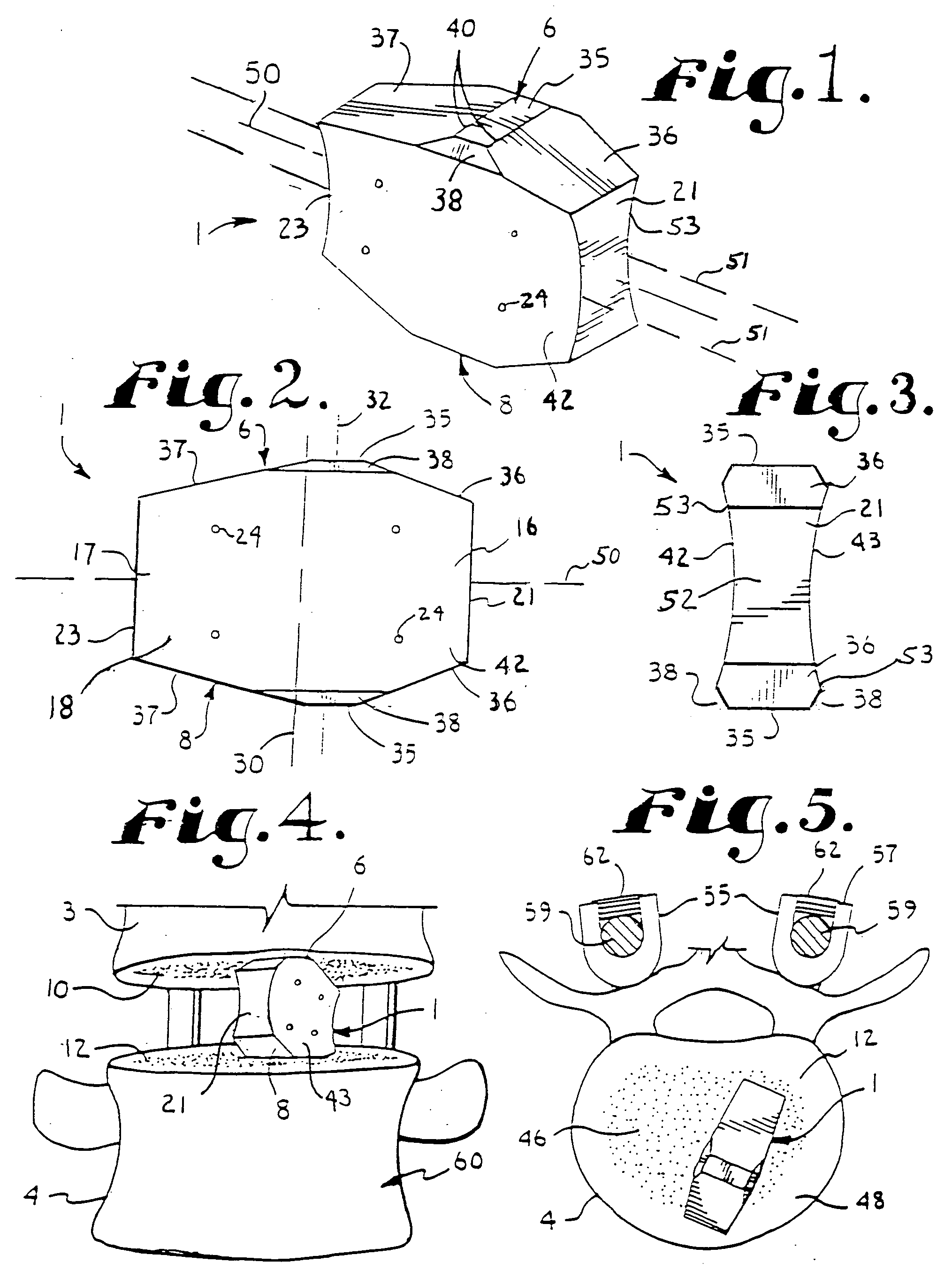
The present invention provides an interbody spacer device for placement between adjacent vertebrae in the spine. The device has a convex or sloped shape that matches the concave shape of the vertebrae and promotes spinal stability and alignment. The device has mirror image convex surfaces that engage the vertebrae and provide maximum surface contact to reduce subsidence and promote bone growth. The device also has lateral sides that are partially cylindrical in shape to reduce weight and volume. The device can be used alone or in conjunction with other implants such as bone screws and rods to secure the position of the device and promote bone growth.

Problems solved by technology

The vertebrae may also become compressed or otherwise damaged.
Vertebrae often become too closely spaced anteriorly due especially to age and other factors that generally produces an abnormal and undesirable curvature with respect to lordosis or kyphosis.
Such devices obviously require removal of bone, but it is preferred that the vertebrae be left as whole as possible so such removal is not desirable.
Such subsidence results from contact pressure of the interbody spacer relative to an engaging surface of a vertebra, since part of the bone is somewhat spongy in nature, especially near the center of the upper and lower surfaces of the bones.
As noted above, age and injury cause the vertebrae to somewhat anteriorly collapse over time.

Method used


Image

  • Vertebral interbody spacer
  • Vertebral interbody spacer
  • Vertebral interbody spacer

Examples


Embodiment Construction

[0030] As required, detailed embodiments of the present invention are disclosed herein; however, it is to be understood that the disclosed embodiments are merely exemplary of the invention, which may be embodied in various forms. Therefore, specific structural and functional details disclosed herein are not to be interpreted as limiting, but merely as a basis for the claims and as a representative basis for teaching one skilled in the art to variously employ the present invention in virtually any appropriately detailed structure.

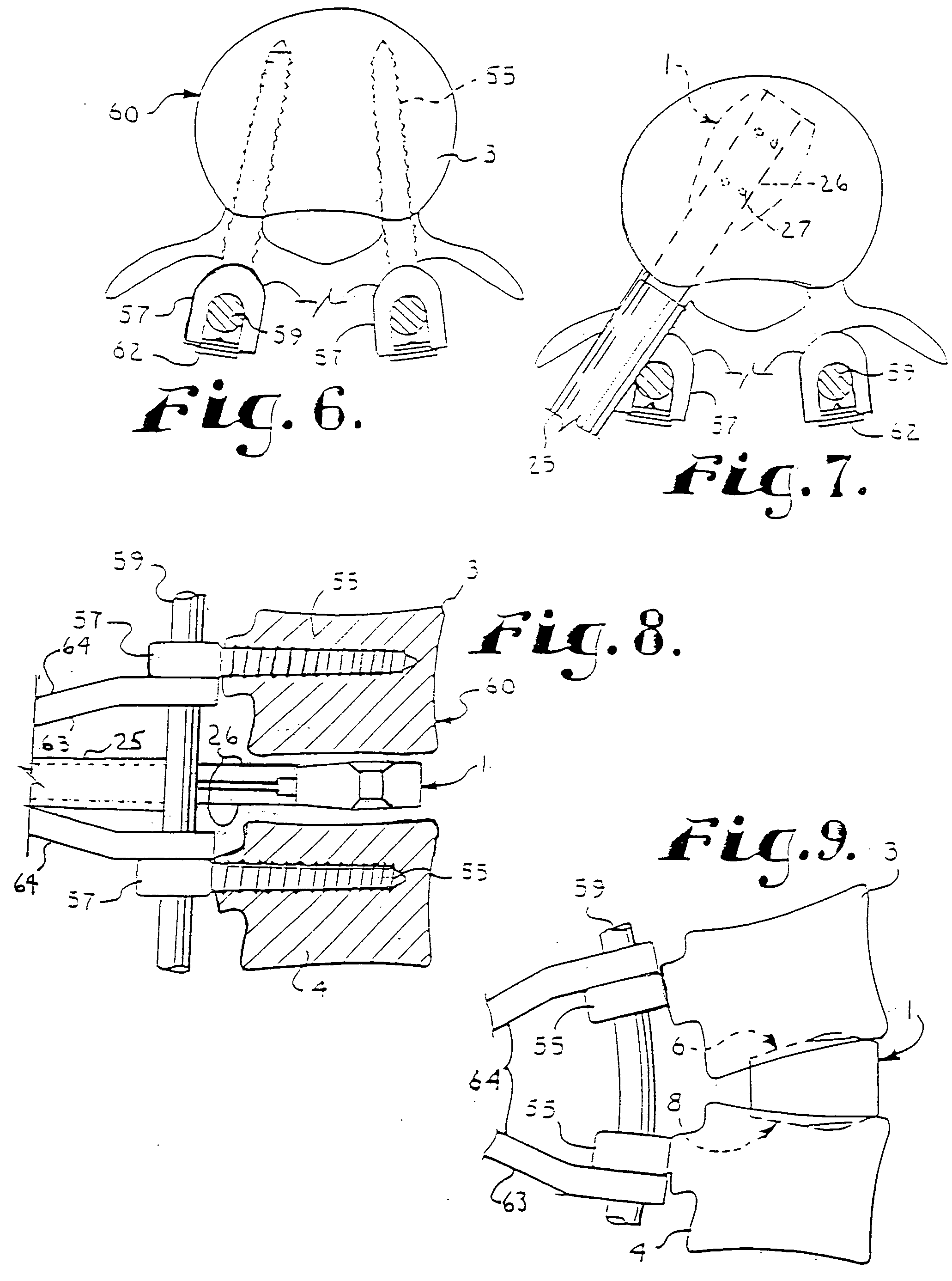
[0031] The reference numeral 1 generally designates a convex spinal fusion interbody spacer device which embodies the present invention. The device 1 is used to maintain proper spacing between a pair of adjacent vertebrae 3 and 4 of a human spine as a replacement for the intervertebral disc and to promote fusion between the vertebrae 3 and 4, preferably in conjunction with other implants, as noted below.

[0032] In particular, the device 1 has a superior (or...


PUM


Abstract

A spinal fusion interbody spacer device has a solid central core positioned between laterally opening opposed concave side surfaces. The device includes spaced apart superior and inferior abutment surfaces which are convexly arced. The spacer device is implanted between a pair of adjacent vertebrae by insertion in a tipped-over orientation and then reoriented to an upright orientation for engagement of the abutment surfaces by facing surfaces of the vertebrae.

Description

BACKGROUND OF THE INVENTION [0001] The present application is directed to an interbody device for implantation between a pair of adjacent vertebrae in order to provide support to the vertebrae and / or promote bone fusion between the vertebrae and, in particular, to a non threaded interbody device having opposed concave sides and a solid core. [0002] In the human spine the pad or disc between vertebrae is sometimes damaged or deteriorates due to age, disease, injury, or congenital defect. The vertebrae may also become compressed or otherwise damaged. Vertebrae often become too closely spaced anteriorly due especially to age and other factors that generally produces an abnormal and undesirable curvature with respect to lordosis or kyphosis. Because of this, surgery is sometimes utilized to place spacers or interbody devices between the vertebrae which provide proper spacing of the vertebrae and which also promote fusion between the vertebrae. When a device of this type is utilized for ...

Claims


Application Information

Patent Timeline
Patent Type & Authority Applications(United States)
IPC IPC(8): A61F2/00A61F2/28A61F2/44A61F2/46
CPCA61F2/28A61F2310/00359A61F2/4611A61F2002/30112A61F2002/30169A61F2002/30237A61F2002/3028A61F2002/30383A61F2002/448A61F2002/4627A61F2002/4628A61F2220/0025A61F2230/0004A61F2230/0047A61F2230/0063A61F2230/0069A61F2310/00017A61F2310/00341A61F2/4455
Inventor JACKSON, ROGER P.
Owner WARSAW ORTHOPEDIC INC
Learn More