Device and method to provide air circulation space proximate to insulation material

a technology of air circulation space and thermal insulation material, which is applied in the direction of walls, artificial islands, building roofs, etc., can solve the problems of increasing the thickness of other types of insulation, affecting the quality of thermal insulation, so as to achieve the effect of minimizing the profile of stacking or rolling

Active Publication Date: 2006-06-15
HETTRICH HANSL
View PDF24 Cites 36 Cited by
  • Summary
  • Abstract
  • Description
  • Claims
  • Application Information

AI Technical Summary

Problems solved by technology

The ever-increasing thickness requirements for fibrous insulation, which is the most commonly-used and economical insulation type for insulating framing cavities, makes adequate ventilation of this insulation more difficult to achieve.
Increased thickness of other types of insulation, such as rigid foams and the like, also present ventilation problems, particularly if the foam is porous to any degree.
Use of dark-colored roofing materials only worsens the problem.
If ventilation is inadequate, or non-existent, the heat will not be expelled from the insulation and the effectiveness of the system will be reduced.
However, as the heat is expelled during the night and cools down, the insulation absorbs moisture, because the cool night air is usually relatively damp.
If ventilation is not adequate, insulation can become completely saturated with moisture and ruin drywall, plaster and ceiling finishes, causing interior dripping and risking collapse of the ceiling.
Prolonged and / or frequent water retention can also promote mildew, mold and rotting of the roof structure.
In today's era of more “efficient” building technology with fewer places for air to penetrate to ventilate insulation, wet insulation and the aforementioned mildew and mold problems can become very serious, often affecting the health of occupants exposed to the mold.
However, if any part of the system is faulty, is improperly installed or becomes damaged, moisture can penetrate into the insulation and reduce its effectiveness and / or cause any of the aforementioned problems such as mold.
However, such conventional methods and systems suffer from certain significant deficiencies.
Additionally, because the most popularly used versions of Rafter-Vent products are made of approximately ⅜″ thick styrene foam plastic, it also blocks the escape of heat via conduction from the insulation because the Rafter-Vent product itself is an insulating material.
An additional drawback to the Rafter-Vent product is that it is supplied to a construction site in a nested bundle.
Because it is fragile, very light in weight, and easily broken, and usually sits on the construction site for a long period of time before it is used, construction sites are often littered with pieces of this product.
Once the bundle is opened and not carefully stored, wind can pick up the large, extremely light panels and scatter them causing litter on construction sites and the neighborhoods surrounding them.
However, as is evident from FIG. 6, tightly packed insulation can still force itself into the form of the Rafter-Vent product and block ventilation.
The Rafter-Vent product thus has significant deficiencies because it does not insure a uniform ventilation space and because versions of it are frequently used incorrectly (i.e., “upside-down”) rendering it ineffective for the purpose intended.
However, with increased thicknesses of insulation required, the “patting down” method does not work today, because it is necessary to resist the force of the compressed insulation in order to maintain the ventilation space.
Thus, as is evident from the related art, conventional methods are ineffective for maintaining an insulation space that permits adequate ventilation of insulation material.

Method used


Image

  • Device and method to provide air circulation space proximate to insulation material
  • Device and method to provide air circulation space proximate to insulation material
  • Device and method to provide air circulation space proximate to insulation material

Examples


Embodiment Construction

[0050] Reference will now be made in detail to the present preferred embodiments of the invention, examples of which are illustrated in the accompanying drawings. The methods and corresponding steps of the invention will be described in conjunction with the detailed description of the preferred embodiments of the invention.

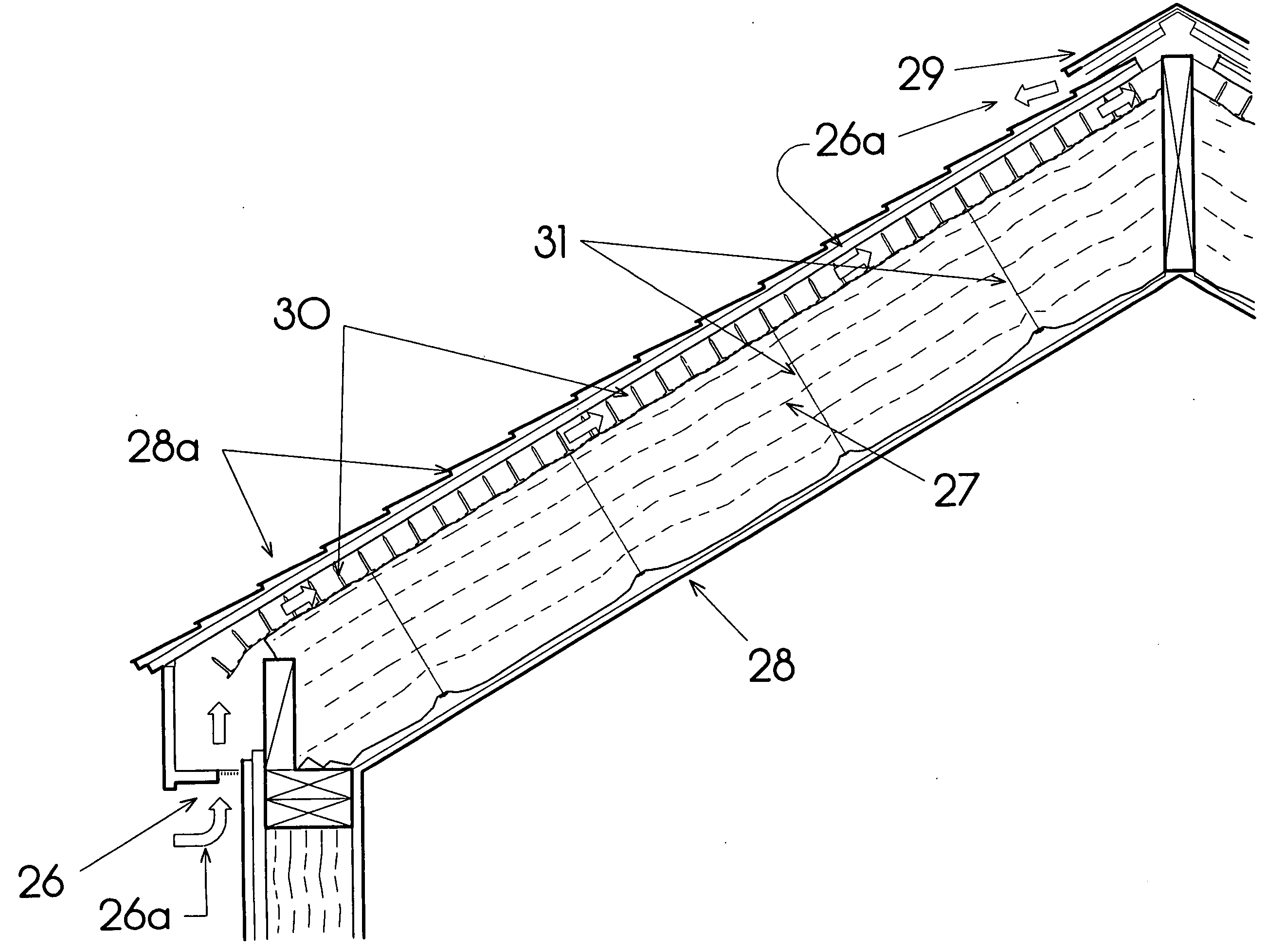
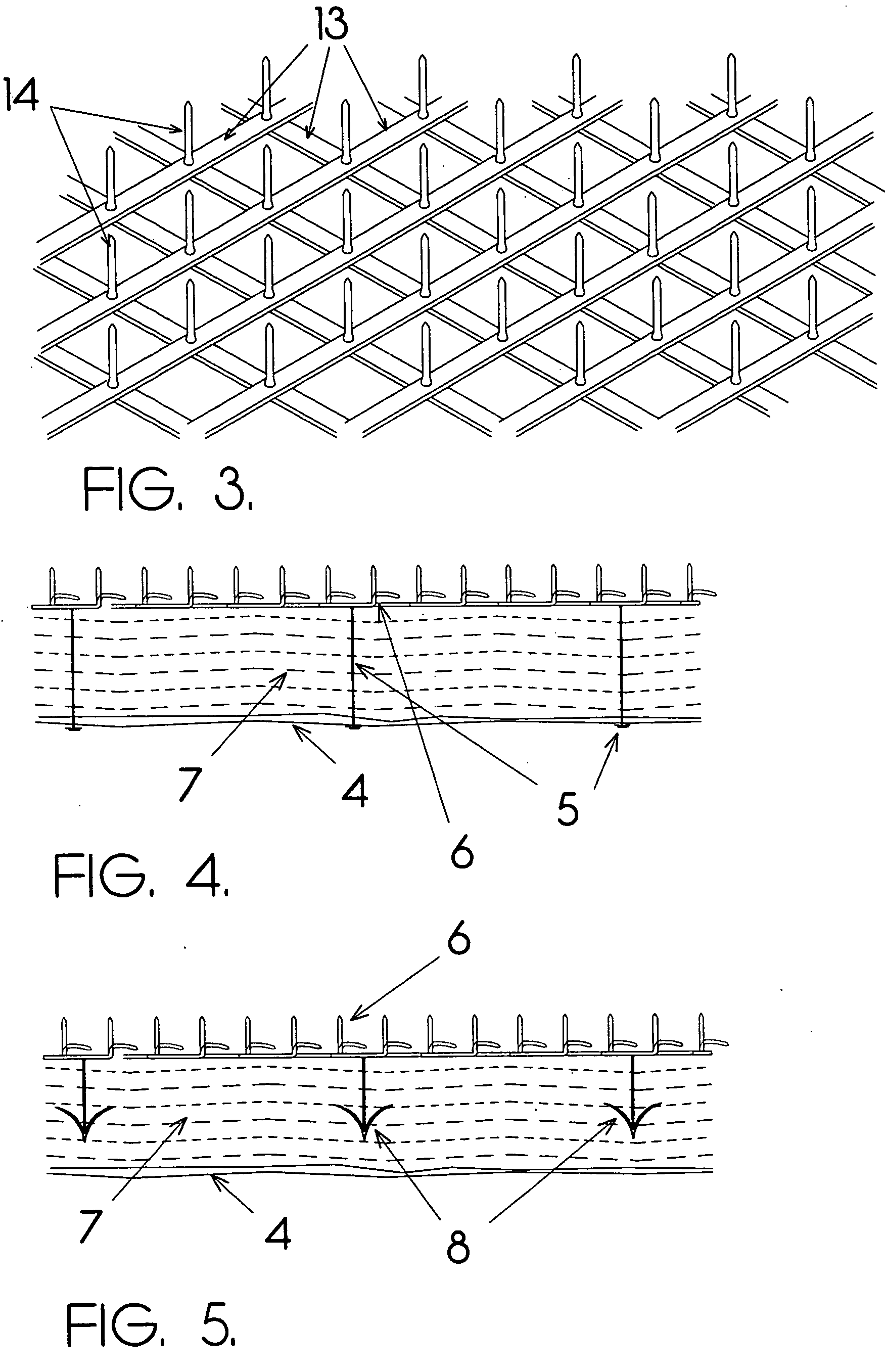
[0051] The methods and devices presented herein may be used for maintaining a ventilation space proximate to insulation material such as thermal insulation. The present invention is particularly suited for maintaining a ventilation space proximate to fibrous thermal insulation, but may be applied to other types of insulation material.

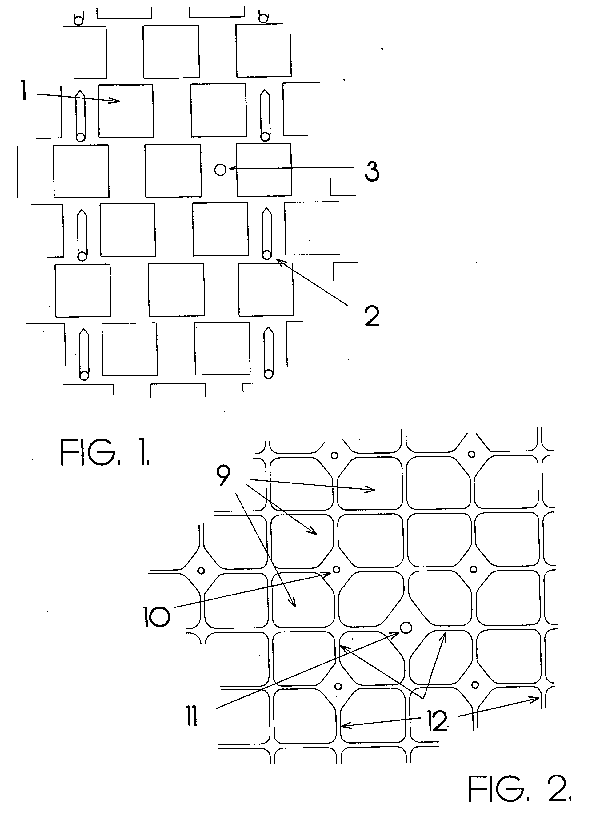
[0052] Spaces made in accordance with this invention are a significant improvement over existing technology. Such devices are suitable for use in roofs and ceilings where ventilation must be maintained in order to expel heat and moisture from thermal insulation. In fact, the device is suitable for any application involving building ...


PUM


Abstract

A spacer device is provided including (1) a body having a plurality of openings defining an openwork, to allow the passage of air therethrough when placed in contact with insulation material, and (2) a plurality of spacer struts fixedly attached to the body. The struts are configured to maintain a predetermined distance between a first side of the insulation material and a building surface. The body and struts act together to define and maintain a space between the first side of the insulation material and the building surface, for example, for ventilation. The building surface can be the bottom face of a roof, an attic floor, wall sheathing or a soundproofed demising wall, for example. The spacer device can be capable of being transported and stored together with, or as a separate item from, the insulation material, and can also be stored in nested layers. The device can also be stored in rolled form. The openwork of the device can additionally or alternatively include a sheet of entangled net filaments.

Description

BACKGROUND OF THE INVENTION [0001] 1. Field of the Invention [0002] The present invention relates primarily to a device for maintaining air circulation space proximate to thermal insulation. Particularly, the present invention is directed to a device to maintain ventilation space above thermal insulation in order to expel heat and moisture from the insulation. [0003] 2. Description of Related Art [0004] Thermal insulation is required to reduce the energy loss from structures for the purposes of maintaining comfortable interior spaces both in heating months and cooling months. The need to reduce the consumption of fossil fuels and the “greenhouse effect” has required the ever-increasing improvement in insulation values. Dimensional lumber sizes used in the framing of structures, and standard dimensions of light steel framing members have not changed significantly in many years. The depth of framing members and therefore the insulation cavity are determined by structural requirements ...

Claims


Application Information

Patent Timeline
Patent Type & Authority Applications(United States)
IPC IPC(8): E04B1/70E04F17/00E04F17/04
CPCE04B1/7662E04B2/7409E04B2/7457E04B2002/7488E04D12/002E04D13/1625E04D13/17E04D13/172E04F17/00E04F17/02E04F17/04
Inventor POLLACK, ROBERT W.
Owner HETTRICH HANSL
Why Eureka
Try Eureka