Monitoring device for rotating body

a technology of rotating bodies and monitoring devices, which is applied in the direction of optical radiation measurement, force measurement by measuring optical property variation, instruments, etc., can solve the problems of wear and noise, inconvenient installation, and inability to supply power to the sensors, so as to achieve accurate detection of defects or breakdowns, easy installation

Inactive Publication Date: 2005-11-17
KOREA INST OF SCI & TECH
View PDF1 Cites 62 Cited by
  • Summary
  • Abstract
  • Description
  • Claims
  • Application Information

AI Technical Summary

Benefits of technology

[0006] It is an object of the present invention to overcome the problems of the prior art and provide a monitoring device for a rota

Problems solved by technology

However, such method has a problem in that it is difficult to supply power to the sensors and to transmit signals from the sensors to a control portion, which is located away from the rotating body.
However, a problem typically results as the contact between a rotor and a stator of the slip ring must be constant.
Further, wear and noise usually occur due to such contact.
Moreover, if the rotating body has a plurality of points to be monitored, such as a turbine, the installation and wiring of the slip ring

Method used


Image

  • Monitoring device for rotating body
  • Monitoring device for rotating body
  • Monitoring device for rotating body

Examples


Embodiment Construction

[0014] Preferred embodiments of the present invention will now be described with reference to the accompanying drawings.

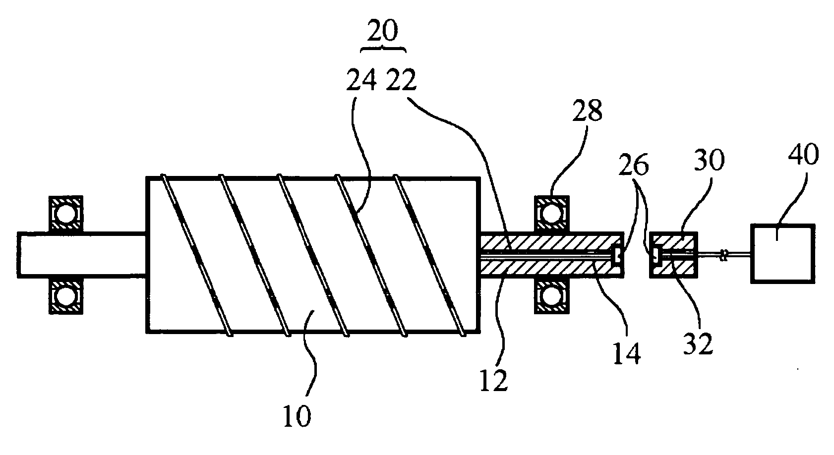
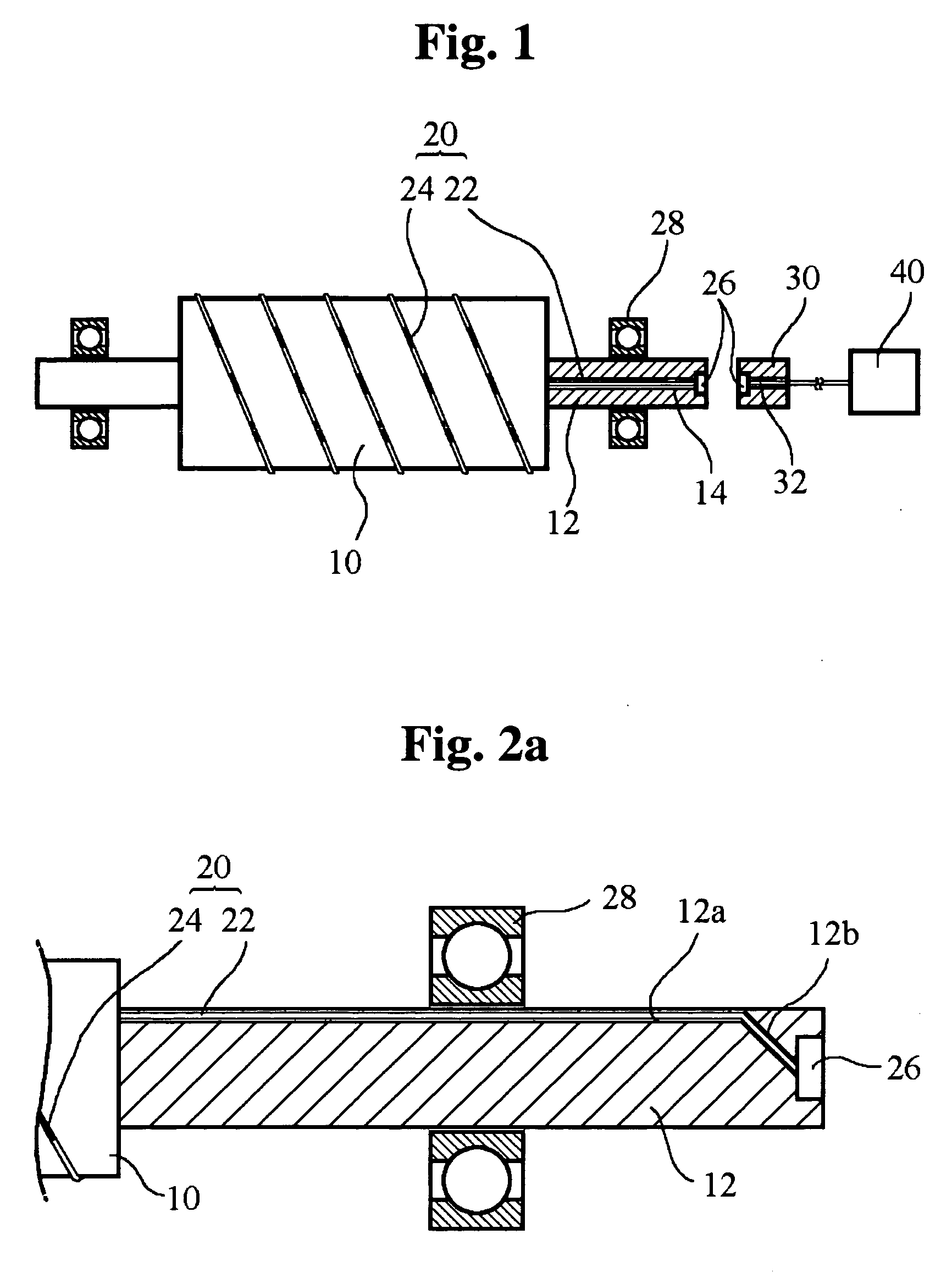
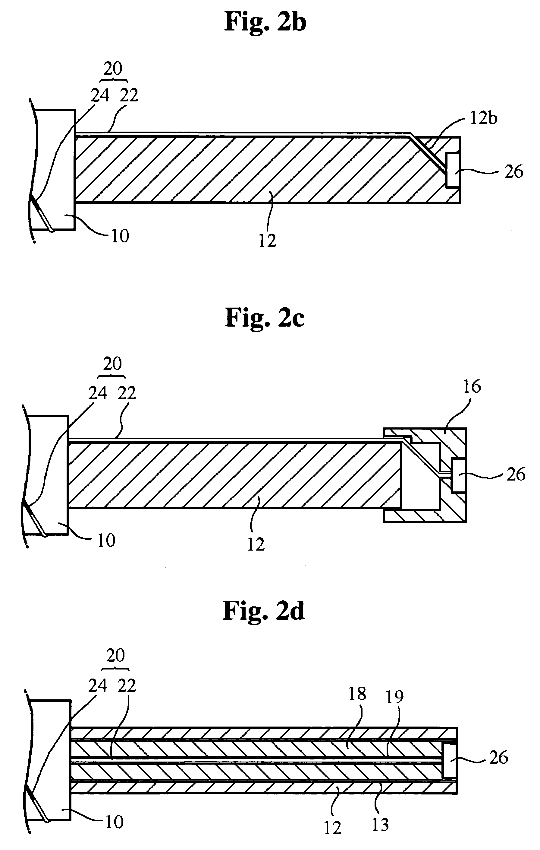
[0015]FIG. 1 schematically shows a flywheel of a flywheel energy storage system to which a monitoring device for a rotating body, which is constructed in accordance with a preferred embodiment of the present invention, is installed.

[0016] As shown in the drawing, rotating shafts 12 are coupled to the central portions of the both ends of a cylindrical flywheel 10. The rotating shafts 12 rotate together with the flywheel 10 while being supported by bearings 28. In order to monitor the flywheel 10 in real time during the rotation, a fiber Bragg grating (FBG) sensor 20 is wound around the flywheel 10 in a spiral shape.

[0017] As already known, the FBG sensor 20 has an optical fiber 22 and a plurality of Bragg gratings 24, which are formed at the optical fiber 22. When light passes through the FBG sensor 20, each of the Bragg gratings 24 reflects the light that has th...


PUM


Abstract

A fiber Bragg grating (FBG) sensor is mounted to a rotating body, which is supported by a rotating shaft mounted rotatably with respect to a fixed element. The FBG sensor extends along the rotating shaft, one end of which is disposed at the center of the end of the rotating shaft. An optical fiber is mounted to the fixed element, one end of which is disposed opposite to the end of the FBG sensor, apart from the FBG sensor. Light emitted from a broadband light source passes through the optical fiber and is transmitted to the FBG sensor across a gap between the optical fiber and the FBG sensor. The FBG sensor reflects light with frequencies corresponding to deformation of the rotating body. A data processing unit receives the reflected light and calculates the deformation of the rotating body based thereupon.

Description

FIELD OF THE INVENTION [0001] The present invention relates to a monitoring device for a rotating body, and more particularly to a monitoring device which detects defects or breakdowns of a rotating body, such as a flywheel, a rotor of a helicopter, etc., by using a fiber Bragg grating sensor. BACKGROUND OF THE INVENTION [0002] A rotating body is an important component of a mechanical apparatus, such as a flywheel of a flywheel energy storage system, a rotor of a helicopter, a turbine blade and so on. Therefore, it is very important to monitor the rotating body to detect any defects or breakdowns in order to prevent unexpected accidents. One method of monitoring the rotating body during operation is to mount sensors like strain-gauges directly to the rotating body. However, such method has a problem in that it is difficult to supply power to the sensors and to transmit signals from the sensors to a control portion, which is located away from the rotating body. [0003] A slip ring, wh...

Claims


Application Information

Patent Timeline
IPC IPC(8): G01B11/16G01D5/353G01J5/08G01L1/24
CPCG01B11/165G02B6/3604G01L1/246G01D5/35303G01B11/18A47J37/0718A47J36/04A47J37/0754A47J37/0694A47J37/0786
Inventor HWANG, YOHALEE, SANG BAELEE, JONG MIN
Owner KOREA INST OF SCI & TECH
Why Eureka
Try Eureka