Information generation device, information reproduction device, and information recording device
- Summary
- Abstract
- Description
- Claims
- Application Information
AI Technical Summary
Benefits of technology
Problems solved by technology
Method used
Image
Examples
embodiment 1
(I) Embodiment 1
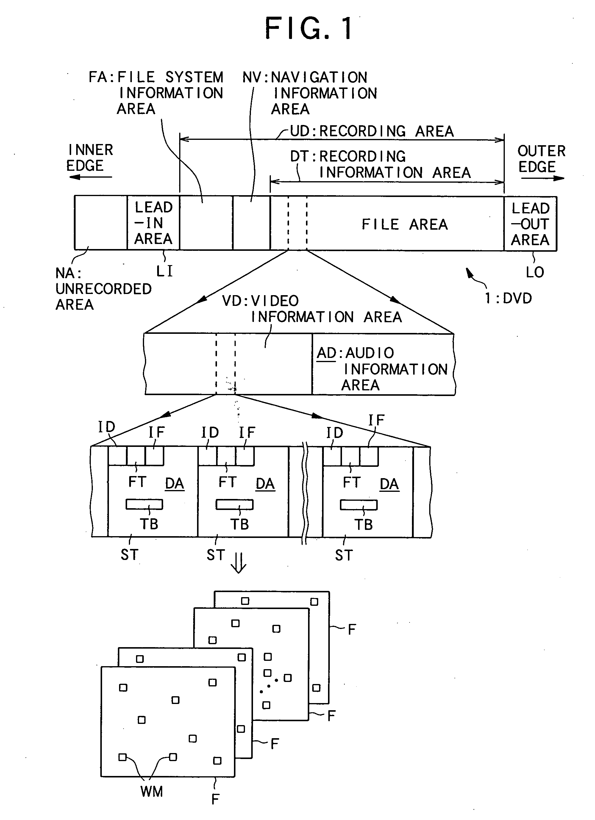
[0107] Referring to FIGS. 1 to 6, the following will first describe Embodiment 1, in which the present invention is applied to the above reproduction restriction and so on during the distribution of a playback only DVD where information is recorded.
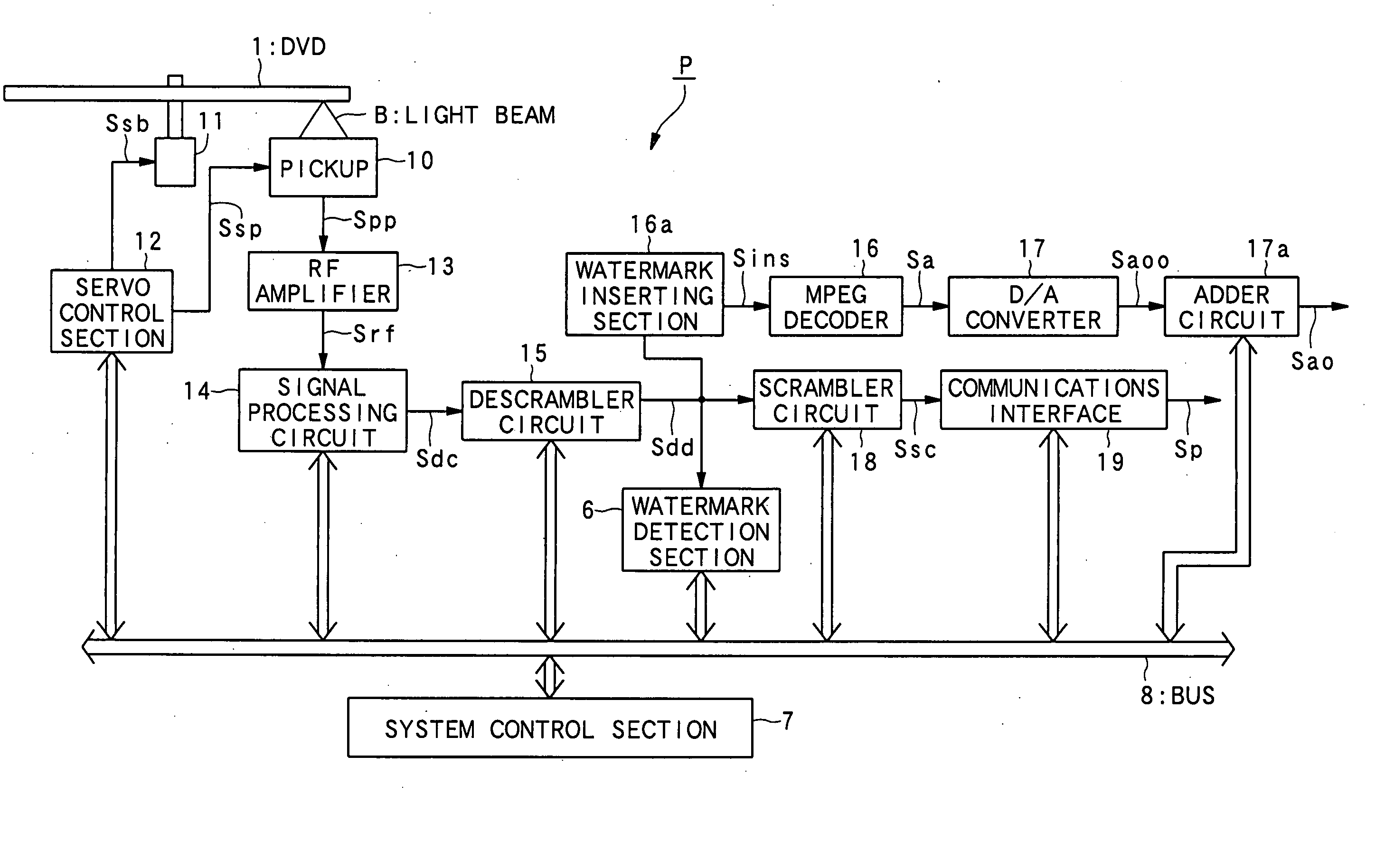
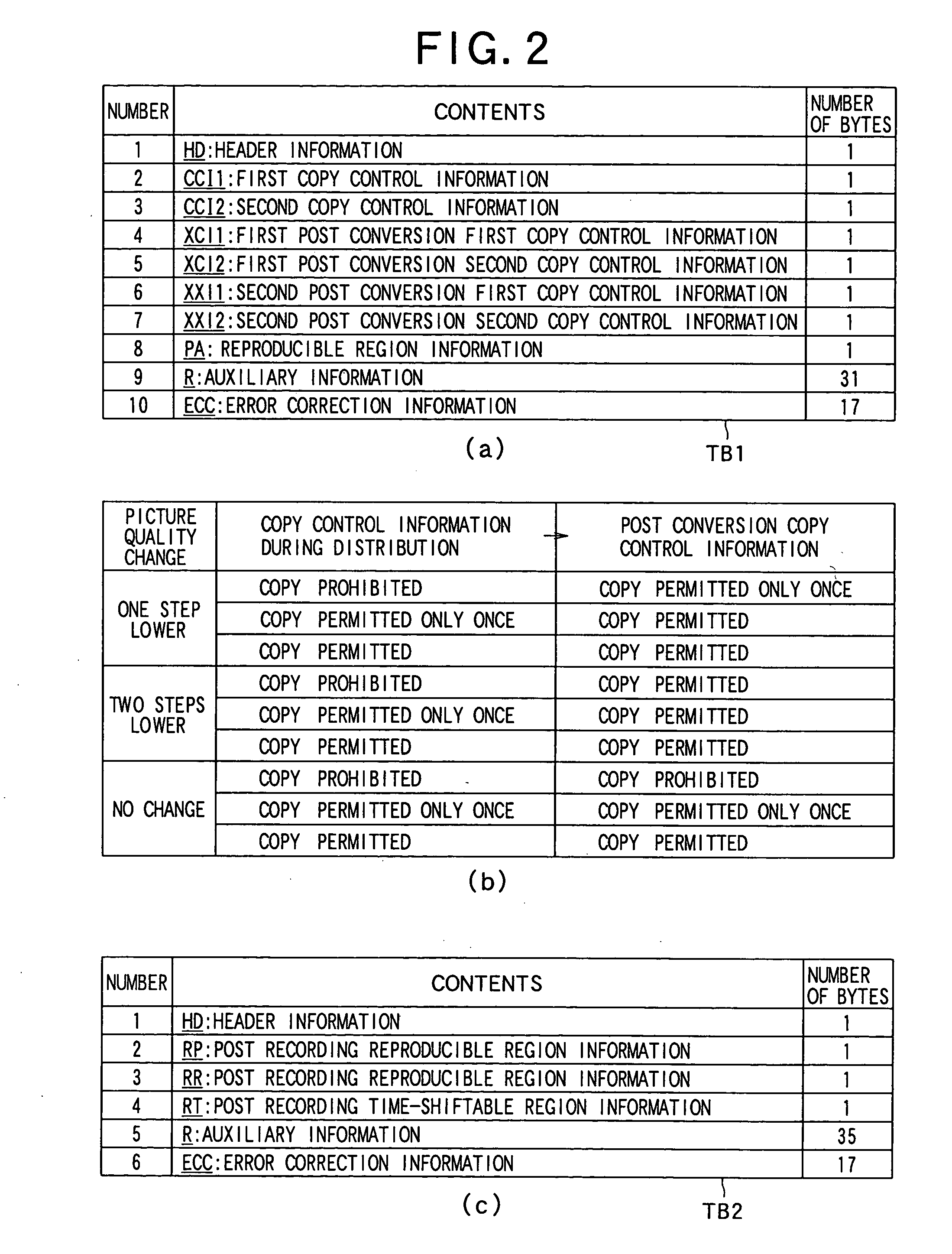
[0108]FIG. 1 is a diagram showing a recording pattern of information on a DVD according to Embodiment 1. FIGS. 2 to 4 are diagrams showing the specific contents of information recorded on the DVD. FIG. 5 is a block diagram showing the schematic configuration of an information reproducing apparatus (DVD player) for reproducing information recorded on the DVD. FIG. 6 is a flowchart showing reproduction performed in the DVD player.
[0109] Referring to FIGS. 1 to 3, the following will first describe the recording format of information recorded on the playback only DVD according to Embodiment 1.
[0110] The following explanation is premised on that information is recorded on the DVD of Embodiment 1, the information indicating c...
embodiment 2
(II) Embodiment 2
[0180] Referring to FIGS. 7 to 14, the following will discuss Embodiment 2, which is another embodiment of the present invention.
[0181] In Embodiment 2 described below, the present invention is applied to the case where the reproduction or recording of recording information is restricted at the destination in an information transmission system for transmitting the recording information, which includes at least image information, via satellite airwaves.
[0182]FIG. 7 is a block diagram showing the schematic configuration of the information transmission system of Embodiment 2. FIG. 8 is a block diagram showing the schematic configuration of a video transmitter included in the information transmission system. FIG. 9 is a diagram showing a format of recording information transmitted in the information transmission system. FIG. 10 is a diagram showing the specific contents of the transmitted recording information. FIG. 11 is a block diagram showing the schematic configur...
embodiment 3
(III) Embodiment 3
[0304] Referring to FIG. 15, the following will describe Embodiment 3 which is another embodiment of the present invention. FIG. 15 is a diagram showing the detailed configuration of an information table according to Embodiment 3.
[0305] In Embodiment 1 and Embodiment 2, the information table TB or TBa includes the first information table TB1 and the second information table TB2 (in case of Embodiment 1) and the first information table TB1a or TB1b and the second information table TB2 (in case of Embodiment 2). In Embodiment 3 described below, a first information table TB1 (TB1a or TB1b) is divided into two with correlation for preventing tampering and is superimposed in recording information. Embodiment 3 is discussed below with an example where the first information table TB1b of Embodiment 2 is divided.
[0306] The configuration and operations of an information transmission system according to Embodiment 3 are completely the same as those of the information trans...
PUM
 Abstract
Description
Claims
Application Information
 - R&D
- Intellectual Property
- Life Sciences
- Materials
- Tech Scout
- Unparalleled Data Quality
- Higher Quality Content
- 60% Fewer Hallucinations
Browse by: Latest US Patents, China's latest patents, Technical Efficacy Thesaurus, Application Domain, Technology Topic, Popular Technical Reports.
© 2025 PatSnap. All rights reserved.Legal|Privacy policy|Modern Slavery Act Transparency Statement|Sitemap|About US| Contact US: help@patsnap.com


