Data transceiver and data transceiver system

a transceiver and data technology, applied in the field of data transceivers and data transceivers, can solve the problems of inpractical protection against illegal copying by adding encryption circuits, the drawback of digital av data, and the inability to easily copy contents, etc., and achieve the effect of increasing the circuit scal

Inactive Publication Date: 2005-01-13
PANASONIC CORP
View PDF1 Cites 18 Cited by
  • Summary
  • Abstract
  • Description
  • Claims
  • Application Information

AI Technical Summary

Benefits of technology

[0027] It is therefore an object of the present invention to provide a 1394 LSI capable of protecting copyright of digital AV content data on a 1394 bus even when the LSI is connected to a wireless communication system, without increasing the circuit scale.

Problems solved by technology

However, the digital AV data has the drawback of “easiness of illegal copying of its contents”.
Thus, protection against illegal copying by adding encryption circuits is not practical.

Method used


Image

  • Data transceiver and data transceiver system
  • Data transceiver and data transceiver system
  • Data transceiver and data transceiver system

Examples


embodiment 1

[0116] Embodiment 1

[0117] Hereinafter, a data transceiver according to a first embodiment of the present invention will be described with reference to the drawings.

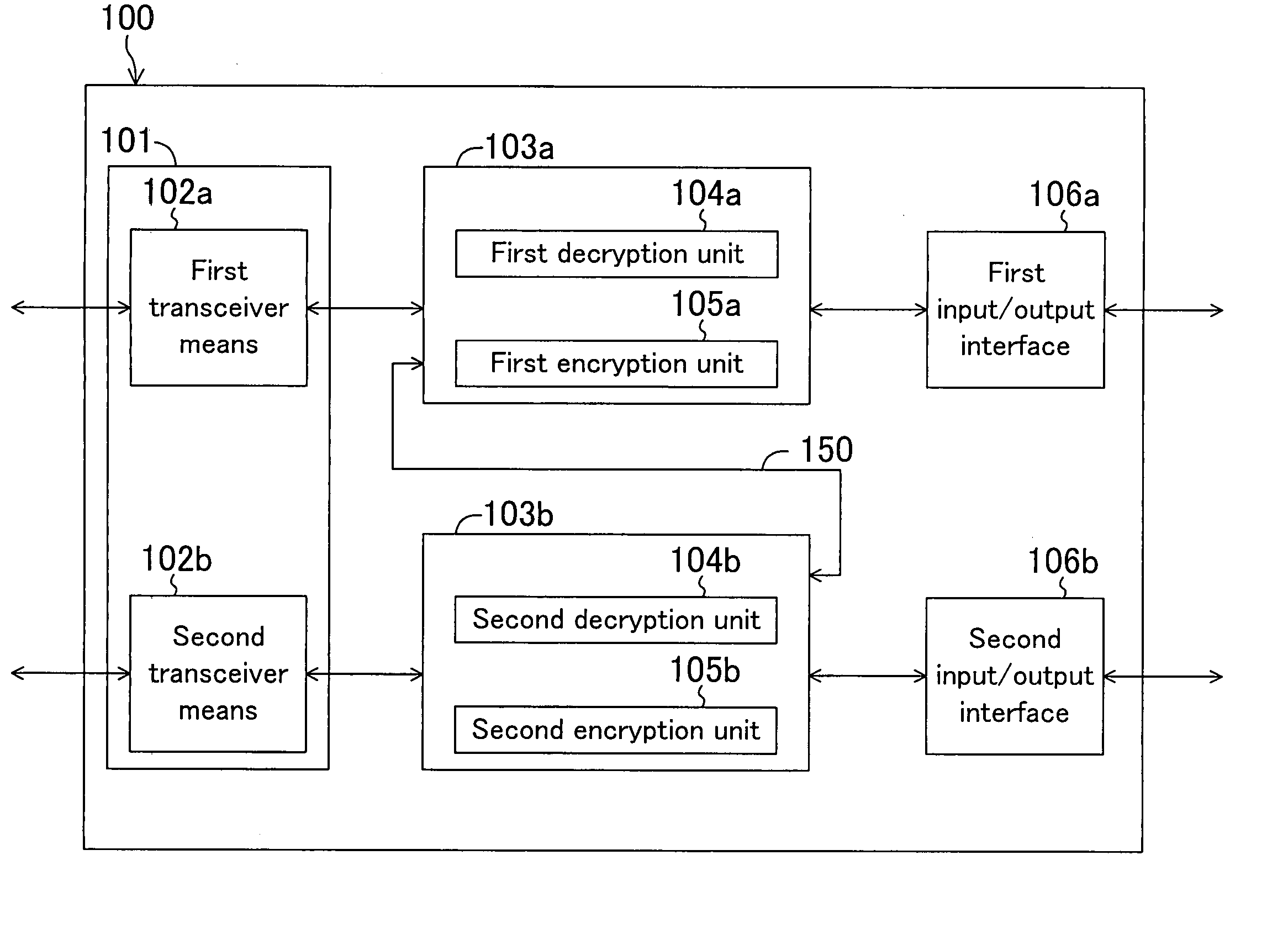
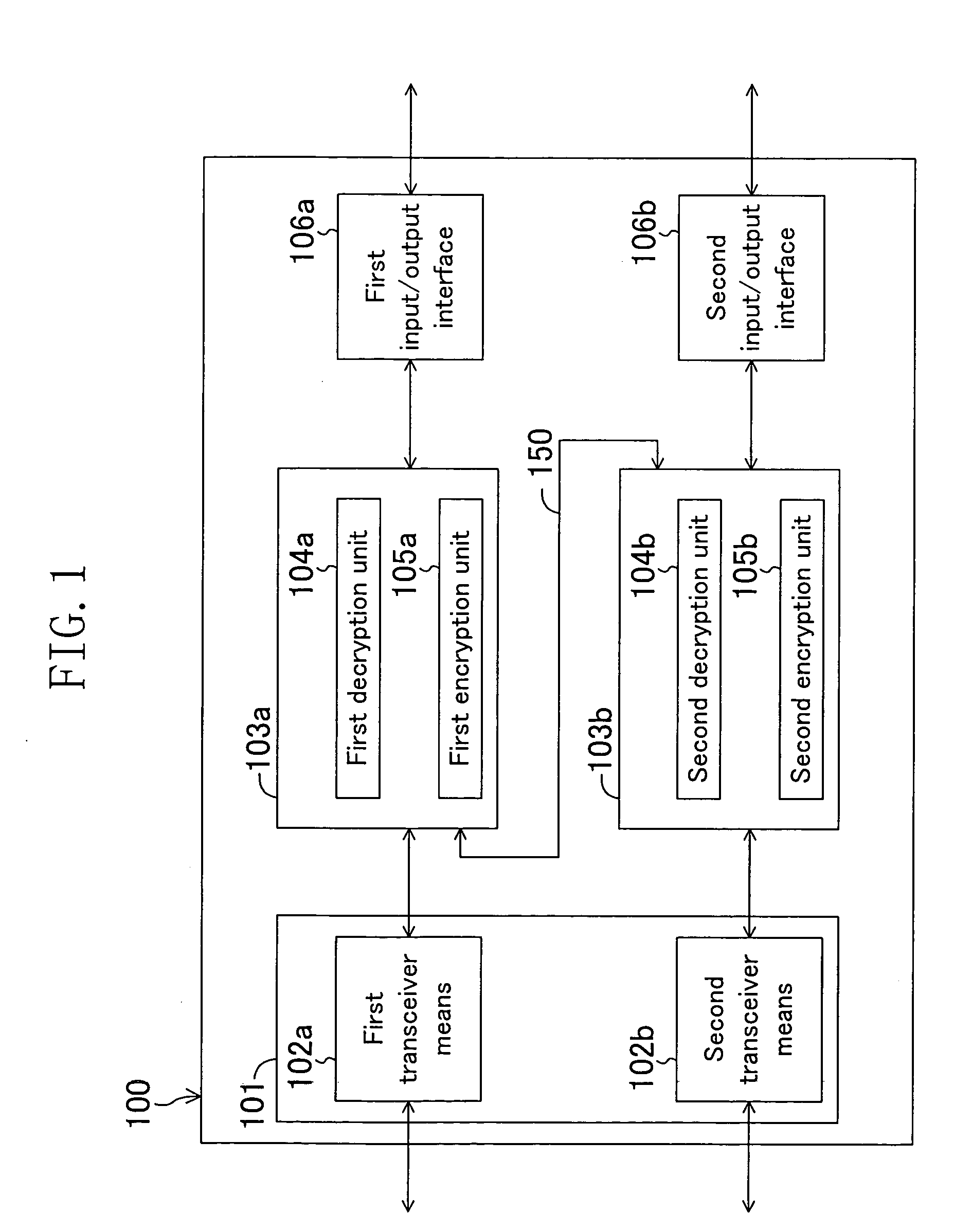
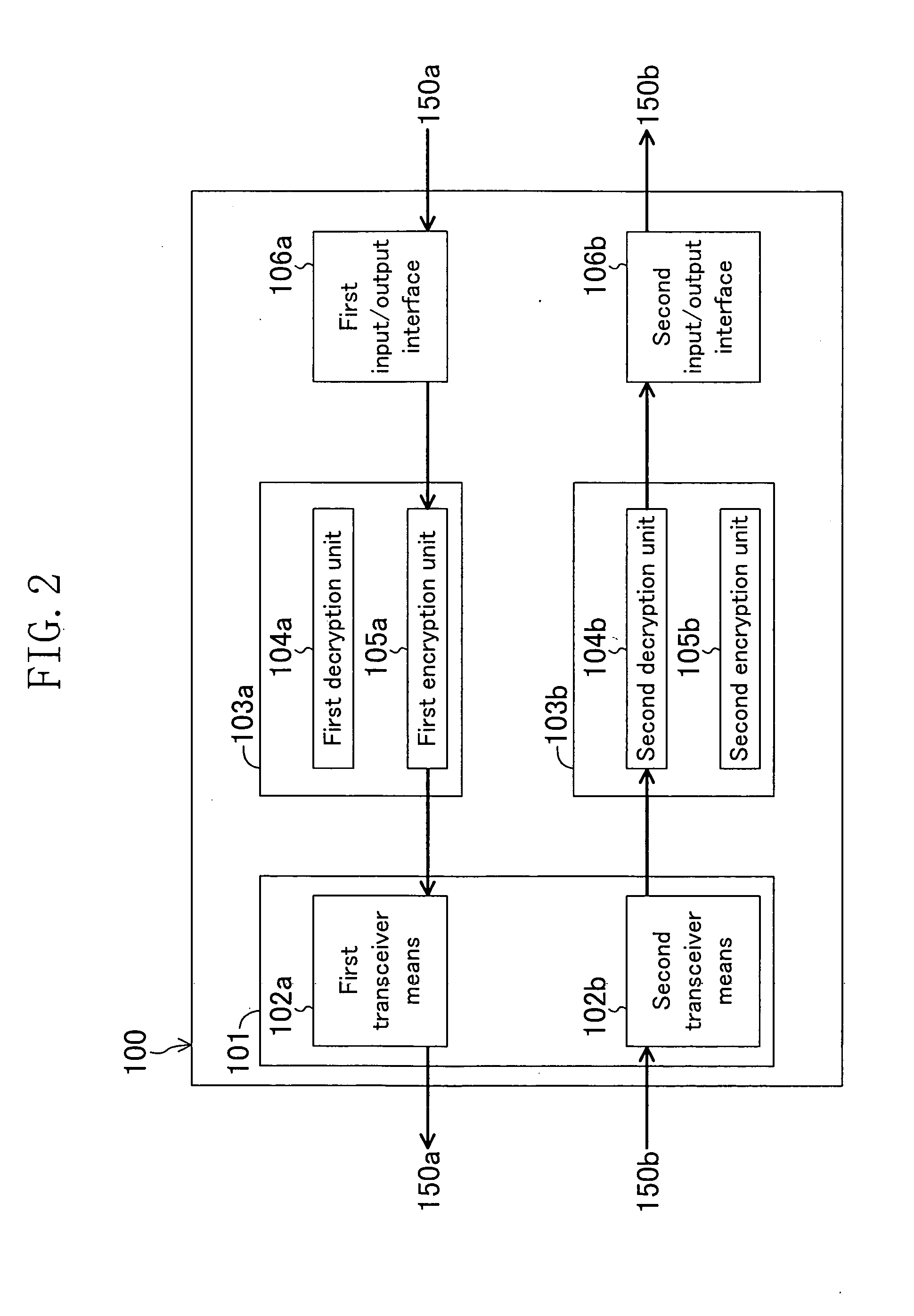
[0118]FIG. 1 is a block diagram showing a configuration of the data transceiver of the first embodiment.

[0119] As shown in FIG. 1, the data transceiver 100 includes: a transceiver means 101 for transmitting and receiving data; first and second encrypting / decrypting means 103a and 103b for encrypting and decrypting data; and first and second input / output interfaces 106a and 106b for input and output of data.

[0120] The transceiver means 101 further includes a first transceiver means 102a and a second transceiver means 102b. The first encrypting / decrypting means 103a includes a first decryption unit 104a for decrypting data and a first encryption unit 105a for encrypting data. The second encrypting / decrypting means 103b includes a second decryption unit 104b for decrypting data and a second encryption unit 105b for encryp...

embodiment 2

[0145] Embodiment 2

[0146] Hereinafter, a data transceiver according to a second embodiment of the present invention will be described with reference to the drawings.

[0147] The data transceiver of the second embodiment is characterized by further including two selectors in addition to the configuration of the data transceiver 100 of the first embodiment shown in FIG. 1. FIG. 7 shows a configuration of the data transceiver of the second embodiment.

[0148]FIG. 7 is a block diagram showing the configuration of the data transceiver of the second embodiment. In FIG. 7, the same members as those of the data transceiver 100 of the first embodiment shown in FIG. 1 are identified by the same reference numerals.

[0149] As shown in FIG. 7, the data transceiver 200 includes: a first selector 120a on a data transmission path between a first transceiver means 102a and a first encrypting / decrypting means 103a; and a second selector 120b on a data transmission path between a second encrypting / decry...

modified example 1

[0163] (Modified Example 1 of Embodiment 2)

[0164] Hereinafter, a data transceiver according to a first modified example of the second embodiment will be described with reference to the drawings.

[0165]FIG. 9 is a block diagram showing a configuration of the data transceiver of the first modified example of the second embodiment. In FIG. 9, the same members as those of the data transceiver 200 of the second embodiment shown in FIG. 7 are identified by the same reference numerals.

[0166] As shown in FIG. 9, the first modified example of the second embodiment is characterized by further including a selector controlling section 121 in addition to the configuration of the data transceiver 200 shown in FIG. 7.

[0167] The selector controlling section 121 controls the first and second selectors 120a and 120b, thereby determining data transmission paths to be selected by the first and second selectors 120a and 120b.

[0168] Hereinafter, operation of the selectors controlled by the selector co...


PUM


Abstract

A data transceiver includes: at least first and second encrypting / decrypting means each for encrypting and decrypting data; and transceiver means for transmitting and receiving data. In a first transmission mode, first transmission data encrypted by the first or second encrypting / decrypting means is transmitted by the transceiver means. In a first reception mode, first received data received by the transceiver means is decrypted by the first or second encrypting / decrypting means. In a second transmission mode, second transmission data decrypted by the first encrypting / decrypting means is encrypted by the second encrypting / decrypting means and then is transmitted by the transceiver means. In a second reception mode, second received data received by the transceiver means is decrypted by the second encrypting / decrypting means and then is encrypted by the first encrypting / decrypting means.

Description

BACKGROUND OF THE INVENTION [0001] The present invention relates to techniques for encrypting content data on networks to prevent illegal copying. [0002] In the recent digital society, digital AV data needs to be transferred by connecting home AV appliances together. As a technique for implementing such a digital AV data transfer, the IEEE 1394 standard has been widely used. The digital AV data thus used has excellent features. For example, the data can be compressed by various compression methods and does not deteriorate even after repetitive replays. However, the digital AV data has the drawback of “easiness of illegal copying of its contents”. Therefore, it has been required to establish a technique for “protection against illegal copying”. With respect to digital AV data which is transferred in compliance with the IEEE 1394 standard, “protections against illegal copying” have been achieved with a DTCP (Digital Transmission Content Protection) technique. [0003] The reasons why th...

Claims


Application Information

Patent Timeline
Patent Type & Authority Applications(United States)
IPC IPC(8): H04L29/06G09C1/00H04N7/16
CPCH04N7/1675H04L63/0464H04N21/43632H04N21/43637H04N21/4367
Inventor MATSUI, TAKAYUKIYANAGISAWA, RYOGO
Owner PANASONIC CORP
Why Eureka
Try Eureka