
Buffer level signaling for rate adaptation in multimedia streaming

a buffer level and rate adaptation technology, applied in the field of multimedia streaming, can solve the problems of dropping packets, affecting the implementation, and affecting the rate of multimedia streaming,

Active Publication Date: 2005-11-17
NOKIA TECHNOLOGLES OY
View PDF10 Cites 52 Cited by
  • Summary
  • Abstract
  • Description
  • Claims
  • Application Information

AI Technical Summary

Benefits of technology

[0027] According to the present invention, the information signaled to the server is further indicative of the highest sequence number received by the client so as to allow the server to determine the data packets in the receiver buffer.

Problems solved by technology

Usually it is the transmission channel that is the bottleneck of the service, both in terms of throughput and in terms of reliability (i.e., if no throughput bitrate guarantee is assumed), but throughput limitations can occur also at the client and / or at the server.
However, they can also be implemented with two separate buffers in a receiver, although such an implementation is not optimum from a delay point of view.
On the other hand, if the incoming data rate is faster than the playout rate, then the receiver buffer space can be exhausted (i.e., buffer overflow), which can result in dropping packets from the buffer in order to make room for new incoming packets.
Yet, if the decoding order and the display order are different, the sender may not be able to derive the status of the buffer and the purpose of the signaling would be defeated.
The server will thus lose track of the receiver buffer status because OBSN is not updated according to the decoding and the removal of packets from the receiver buffer.
However, because the decoding order and the transmission order are not the same in some occasions, the sender may lose track of the receiver buffer.

Method used


Image

  • Buffer level signaling for rate adaptation in multimedia streaming
  • Buffer level signaling for rate adaptation in multimedia streaming
  • Buffer level signaling for rate adaptation in multimedia streaming

Examples


Embodiment Construction

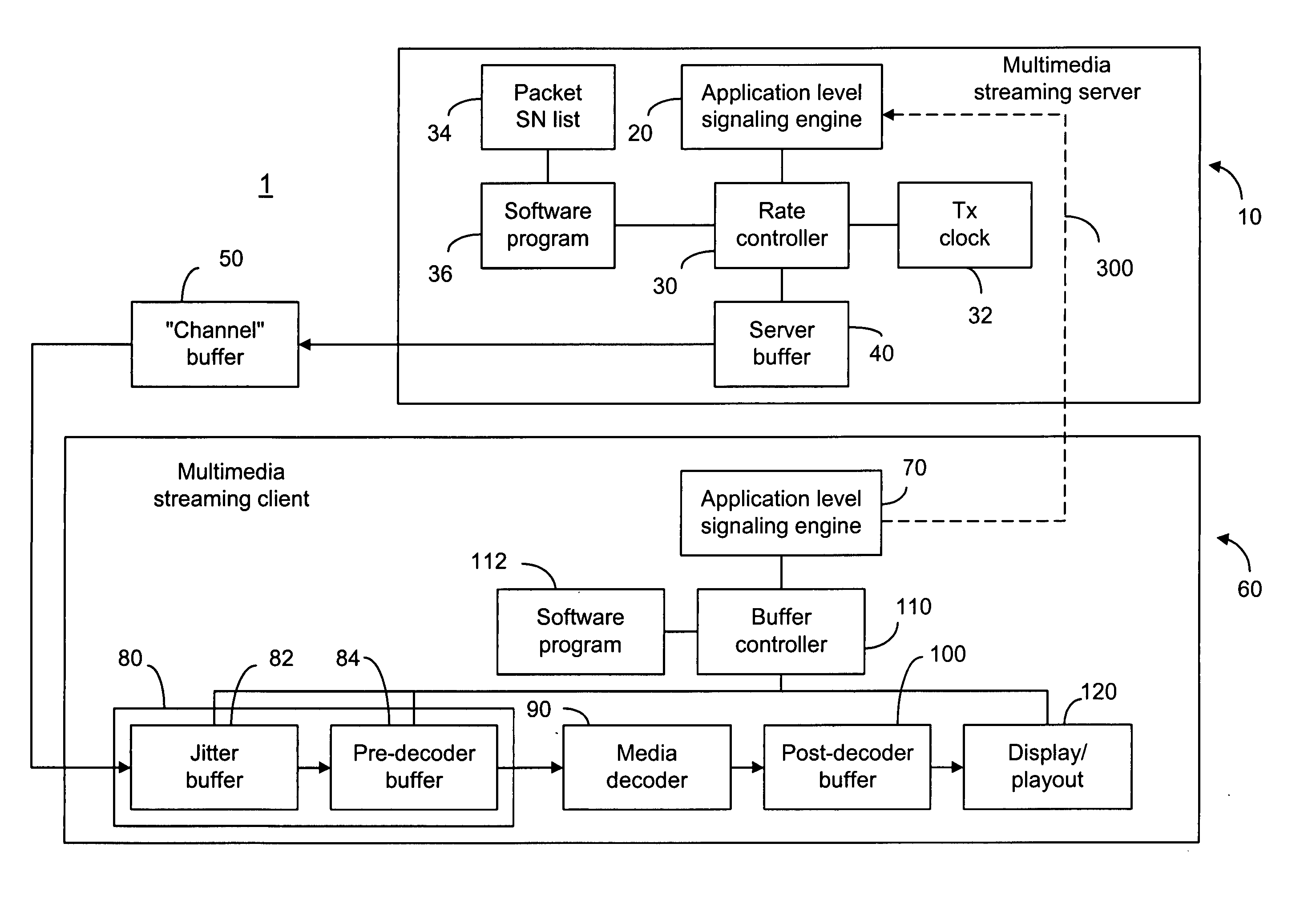
[0064] The present invention provides a method of buffer level signaling so as to allow the server in a multimedia streaming network to perform rate adaptation in codecs such as H.26L, for which packet transmission order is different from decoding order. The buffer level signaling method, according to the present invention, is based on information about the next packet to be decoded. The sequence number of the next packet to be decoded is referred to as NDSN. Several implementations are described below:

IMPLEMENTATION I

[0065] The receiver reports to the sender information of the next packet to be decoded based on the smallest y value. Based on the received NDSN, the server can identify the packet to be decoded next. As such, the sender can derive the correct status of the receiver buffer. Using the set of x and y values given in the background section, this implementation can be illustrated as follows:

[0066] When packets x+4, x+5, x+6 and x+7 have been received, their correspondi...


PUM


Abstract

In a multimedia streaming network where a client has a receiver buffer to store a plurality of packets received from a server so as to compensate for the difference between data transmission amount by the server and data usage amount by the client, the server should be able to adapt the data transmission rate based on the status of the receiver buffer. For rate adaptation purposes, server reconstructs a list of packets in the receiver buffer based on information provided by the client. The information signaled to the server is indicative of the next packet to be decoded in the client. The information can be the sequence number of the next packet to be decoded, the DON number of the next NAL unit to be decoded, or the sequence number of the packet carrying the next NAL unit to be decoded and the DON indicative of the decoding order of that next NAL unit.

Description

FIELD OF THE INVENTION [0001] The present invention relates generally to multimedia streaming and, more particularly, to rate adaptation between a server and a client in multimedia streaming services. BACKGROUND OF THE INVENTION [0002] In a multimedia streaming service, there are three participants involved: a streaming server, a streaming client and a transmission channel or an underlying network. Usually it is the transmission channel that is the bottleneck of the service, both in terms of throughput and in terms of reliability (i.e., if no throughput bitrate guarantee is assumed), but throughput limitations can occur also at the client and / or at the server. [0003] In a real-time streaming system, due to the dynamically changing throughput characteristics of the channel, client and server, the streaming delivery needs to be adaptive in order to maintain a real-time playback experience for the user. The server should adapt the transmission rate to the varying throughput of the syst...

Claims


Application Information

Patent Timeline
Patent Type & Authority Applications(United States)
IPC IPC(8): H04L12/26H04L12/28H04L12/56H04L29/06
CPCH04L29/06027H04L47/263H04L47/30H04L65/80H04L65/4069H04L65/607H04L65/608H04L47/34H04L65/61H04L65/65H04L65/70H04L65/1101
Inventor LEON, DAVIDHANNUKSELA, MISKAAKSU, EMRE BARIS
Owner NOKIA TECHNOLOGLES OY
Learn More