High power semiconductor laser lighting device

a laser lighting and high-power technology, applied in lasers, laser cooling arrangements, laser details, etc., can solve the problems of thermal cooling chips and reduce the heat dissipation efficiency of the second conventional high-power, and achieve the effect of preventing the heat dissipation efficiency from decreasing

a laser lighting and high-power technology, applied in lasers, laser cooling arrangements, laser details, etc., can solve the problems of thermal cooling chips and reduce the heat dissipation efficiency of the second conventional high-power, and achieve the effect of preventing the heat dissipation efficiency from decreasing

US20050254537A1Inactive Publication Date: 2005-11-17EINS TECH

Image

  • High power semiconductor laser lighting device
  • High power semiconductor laser lighting device
  • High power semiconductor laser lighting device

Examples


Embodiment Construction

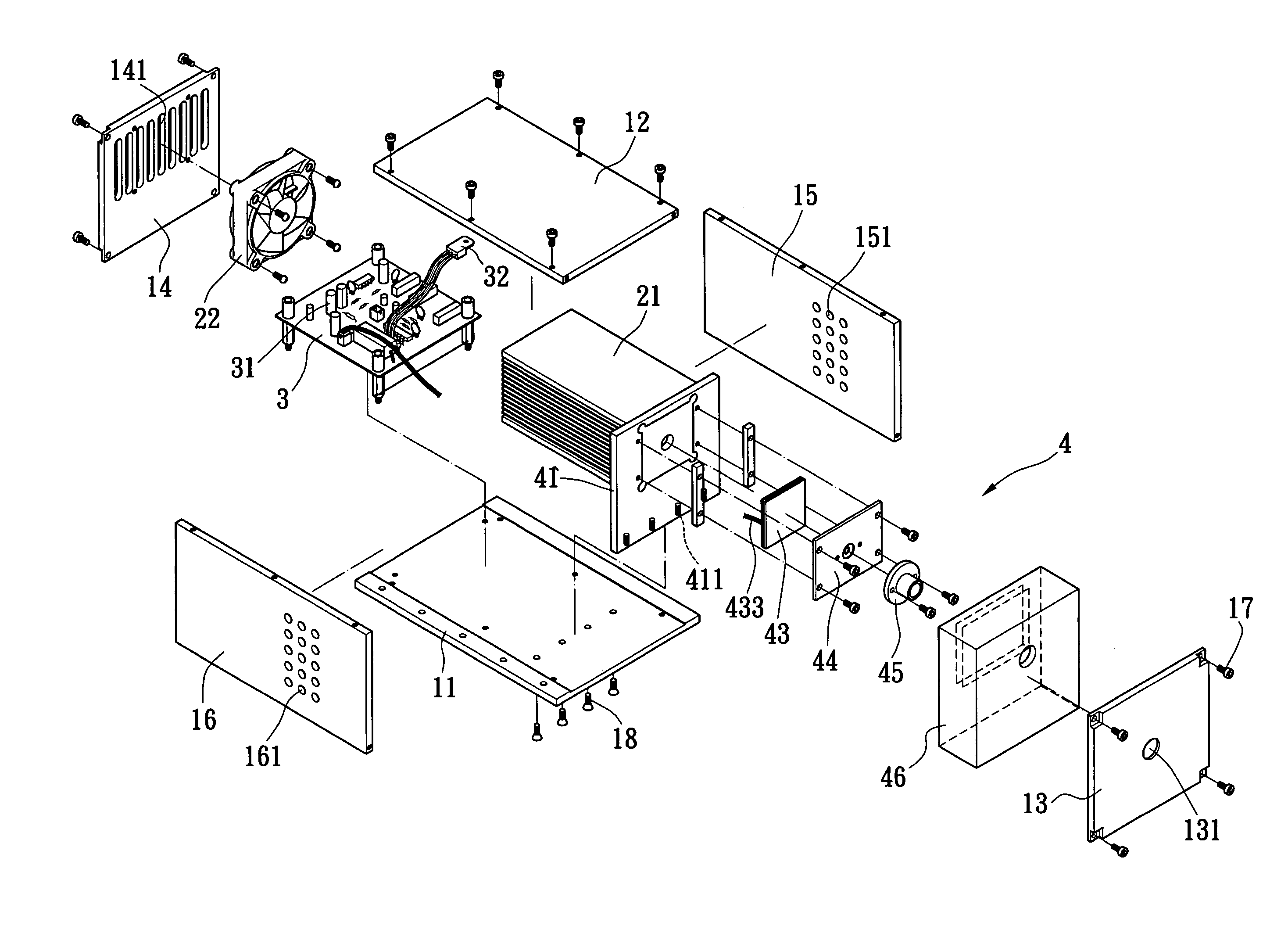
[0023] With respect to FIGS. 4 to 6, the present invention provides a high power semiconductor laser lighting device including a housing 1, a fan module 2, a base 3, and a semiconductor laser constant-temperature module 4.

[0024] The housing 1 includes a bottom wall 11, a top wall 12, a front wall 13, a rear wall 14 and two sidewalls 15, 16 via a plurality of screws 17. The front wall 13 has a lighting hole 131 and a transparent member 132, such as transparent tempered glass, covering the lighting hole 131. The rear wall 14 has an exhaust hole 141 formed therein, and each sidewall 15, 16 includes a plurality of through holes 151, 161 respectively formed therein.

[0025] The fan module 2 is arranged in the exhaust hole 141 of the rear wall 14 in the housing 1. The fan module 2 includes a heat dissipation plate 21, such as an aluminum extrusion heat sink with a plurality of fins disposed thereon, adjacent to a fan 22 to dissipate heat via the exhaust hole 141.

[0026] The base 3 connect...


PUM


Abstract

A high power semiconductor laser lighting device has a housing, a fan module arranged in an exhaust hole in the housing, a base connected to the bottom wall of the housing and disposed on a side of the fan module, and a semiconductor laser constant-temperature module. The base has a driving unit with at least one high power electronic component connected to fins of the fan module. The semiconductor laser constant-temperature module has a metallic partition to enclose a vacuum formed in a front portion of the housing, and a heat insulation layer arranged in the vacuum. The metallic partition has a side connecting the heat dissipation plate and an opposite side connecting a heating portion of a thermoelectric cooling chip, which includes a cooling portion connecting to a semiconductor laser lighting module. The high power semiconductor laser lighting device to keep an output power thereof constant within various environments.

Description

BACKGROUND OF THE INVENTION [0001] 1. Field of the Invention [0002] The present invention relates to a high power semiconductor laser lighting device, and particularly relates to a high power semiconductor laser lighting device with a housing including a semiconductor laser module, a fan module, a driving unit, and the high power semiconductor laser lighting device keep an output power thereof constant within various environments. [0003] 2. Background of the Invention [0004] Referring to FIG. 1, a first conventional high power semiconductor laser lighting device adopted for industrial instruments includes a housing 60, a resilient mount 65, a high power laser module 70, a controlling mask 75, at least one fan 80 and a voltage regulator circuit unit 85. The resilient mount 65 is disposed in a bottom of the housing 60, and has an insulating post 66 arranged in a front portion thereof and an insulating spring 67 arranged in a rear portion thereof. The high power laser module 70 include...

Claims


Application Information

Patent Timeline
17 Nov 2005
Publication
US20050254537A1
IPC
H01S3/04; H01S5/022; H01S5/024
CPC
H01S5/02; H01S5/06837; H01S5/02415; H01S5/02407
Inventors
SU, SHENG-PIN; YU, CHUN-KUN