Condenser microphone

a condenser microphone and microphone technology, applied in the direction of piezoelectric/electrostrictive transducers, microphone structural associations, transducer types, etc., can solve the problem that the method cannot be applied to a microphone, and achieve the effect of preventing the noise caused by strong electromagnetic waves

Inactive Publication Date: 2005-11-17
AUDIO-TECHNICA
View PDF3 Cites 13 Cited by
  • Summary
  • Abstract
  • Description
  • Claims
  • Application Information

AI Technical Summary

Benefits of technology

[0015] According to the present invention, since the microphone cord is connected to the terminal pulled out of the shield case for the circuit board, strong electromagnetic waves applied to the microphone cord do not intrude into the s

Problems solved by technology

However, although being effective for the gun microphone or the like, this method cannot be applied to a microphone in which, as in the conventional

Method used


Image

  • Condenser microphone
  • Condenser microphone
  • Condenser microphone

Examples


Embodiment Construction

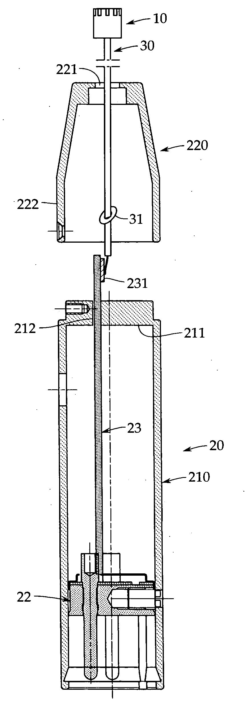
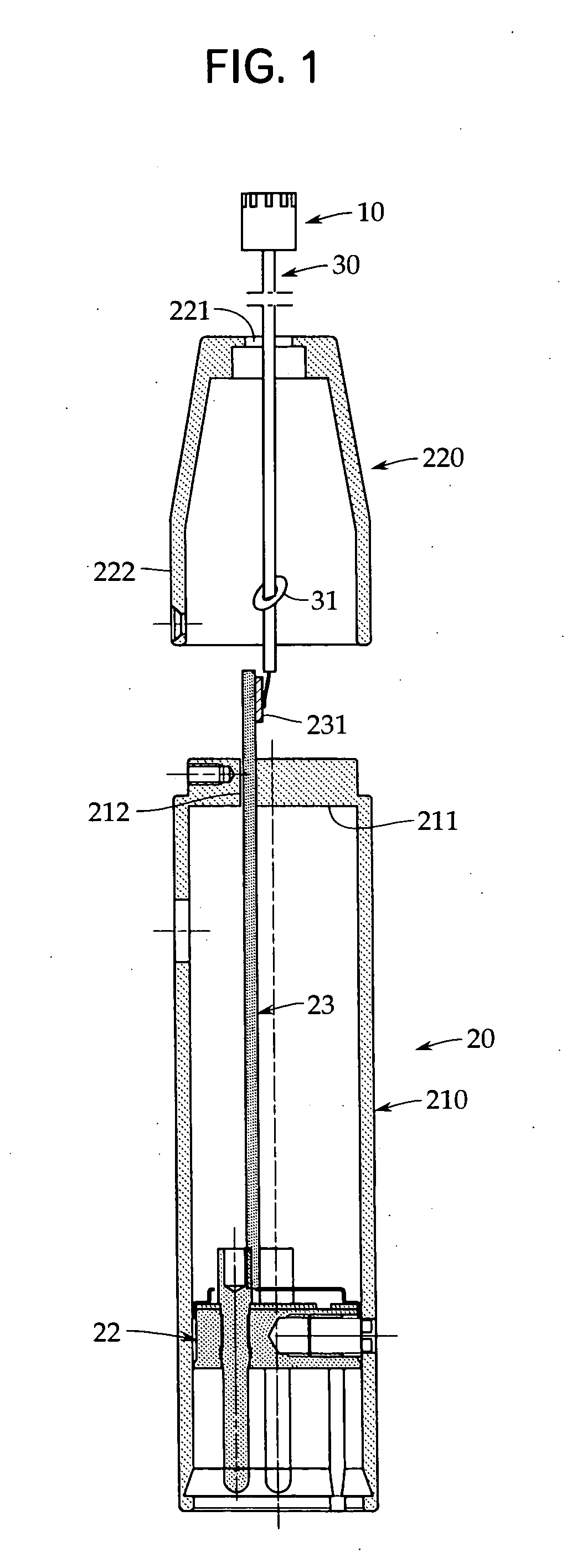
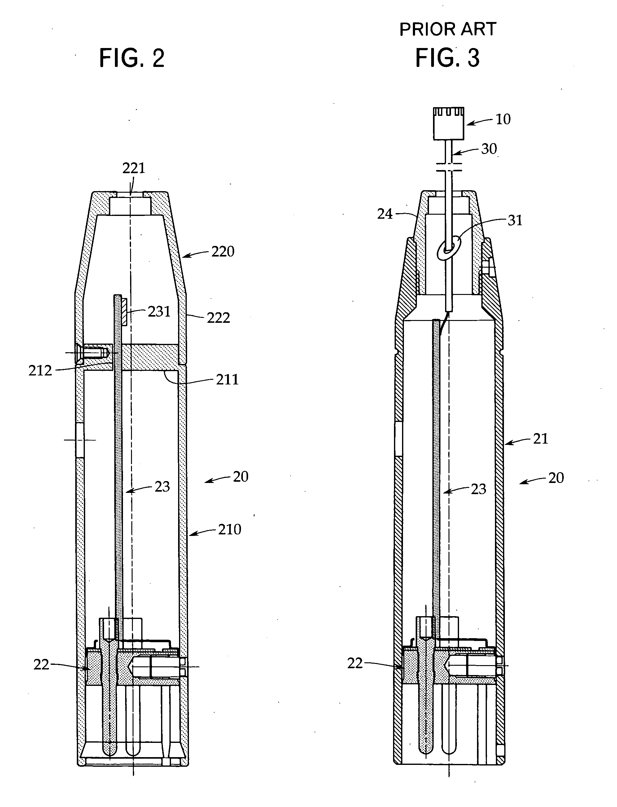
[0019] An embodiment of the present invention will now be described with reference to FIGS. 1 and 2. FIG. 1 is a schematic view showing a state in which a microphone capsule and an audio output section, which are included in a condenser microphone in accordance with the present invention, are connected to each other via a microphone cord. In FIG. 1, the audio output section is shown in a broken sectional view. FIG. 2 is a sectional view showing only the audio output section, which is an essential portion of the present invention. In FIGS. 1 and 2, the same reference numerals are applied to elements that are the same or regarded as the same as the elements in the conventional example explained before with reference to FIG. 3.

[0020] The condenser microphone in accordance with the present invention is a microphone in which a microphone capsule 10 and an audio output section 20 are separated from each other and these elements are connected to each other via a microphone cord 30. Genera...


PUM


Abstract

In a condenser microphone in which a microphone capsule and an audio output section are connected to each other via a microphone cord, strong electromagnetic waves generated by a cellular phone etc. are prevented from being transmitted by the microphone cord and intruding into the audio output section. In a condenser microphone in which a microphone capsule 10 and an audio output section 20, in which a circuit board 23 including an audio output circuit is housed in a shield case 210, are connected to each other via a microphone cord 30, of the circuit board 23, a terminal 231 connected to the microphone cord 30 is arranged on the outside of the shield case 210.

Description

TECHNICAL FIELD [0001] The present invention relates to a condenser microphone in which a microphone capsule and an audio output section are connected to each other by a dedicated microphone cord. More particularly, it relates to a technique for preventing electromagnetic waves generated by a cellular phone etc. from being transmitted by the microphone cord and intruding into the audio output section. BACKGROUND ART [0002] For a gooseneck microphone for conference, a tie clip microphone used by being attached to clothes etc., and the like of the condenser microphones, as shown in FIG. 3, a microphone capsule 10 and an audio output section 20 are separated from each other and are connected to each other by a dedicated microphone cord 30. [0003] In the microphone capsule 10, a condenser microphone unit including a diaphragm and a backplate and an impedance converter therefor, for example, a field effect transistor (FET) are housed (both elements are not shown). The audio output sectio...

Claims


Application Information

Patent Timeline
IPC IPC(8): H04R1/02H04R1/00H04R1/04H04R3/00H04R19/04
CPCH04R19/04H04R1/04
Inventor AKINO, HIROSHI
Owner AUDIO-TECHNICA
Why Eureka
Try Eureka