
Measurement of ion mobility spectra

a technology of mobility spectra and measurement method, which is applied in the field of measuring the mobility spectra of ions, can solve the problems of inability to accept the method, the evaluation procedure using the fourier transformation does not work stably for a noisy detector signal, and the expectation of increasing the signal-to-noise ratio has been disappointing. , to achieve the effect of improving the signal-to-noise ratio, high mobility resolution and strong nois

Active Publication Date: 2012-11-06
BRUKER OPTICS GMBH & CO KG
View PDF18 Cites 8 Cited by
  • Summary
  • Abstract
  • Description
  • Claims
  • Application Information

AI Technical Summary

Benefits of technology

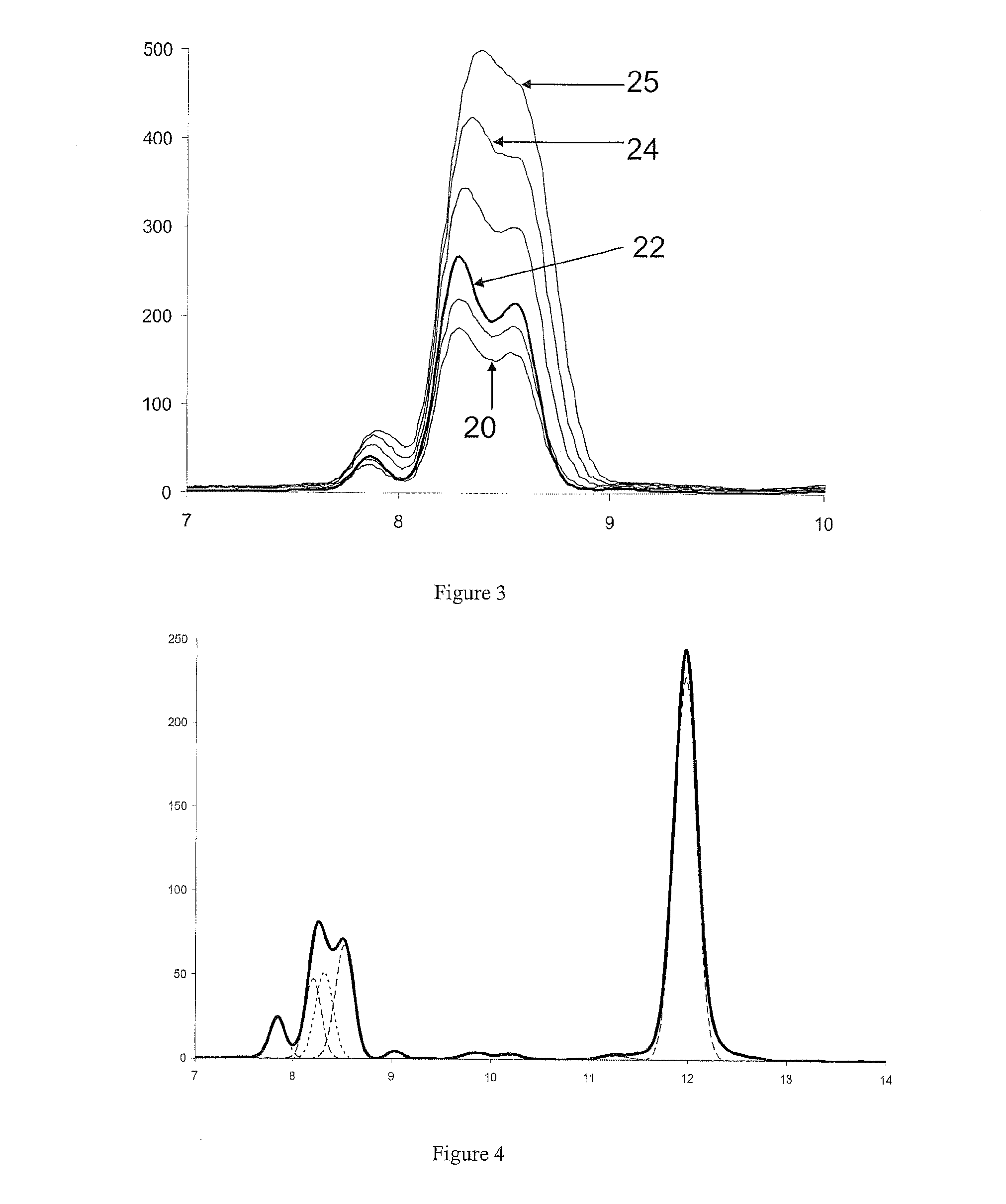
[0022]Advantageously, the method generates a relatively noise-free mobility spectrum with good mobility resolution.
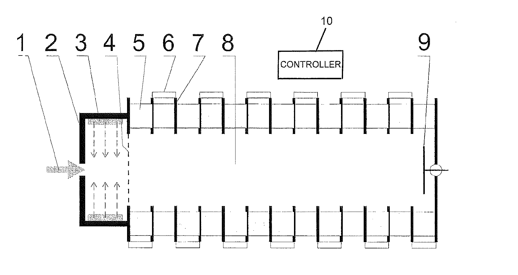
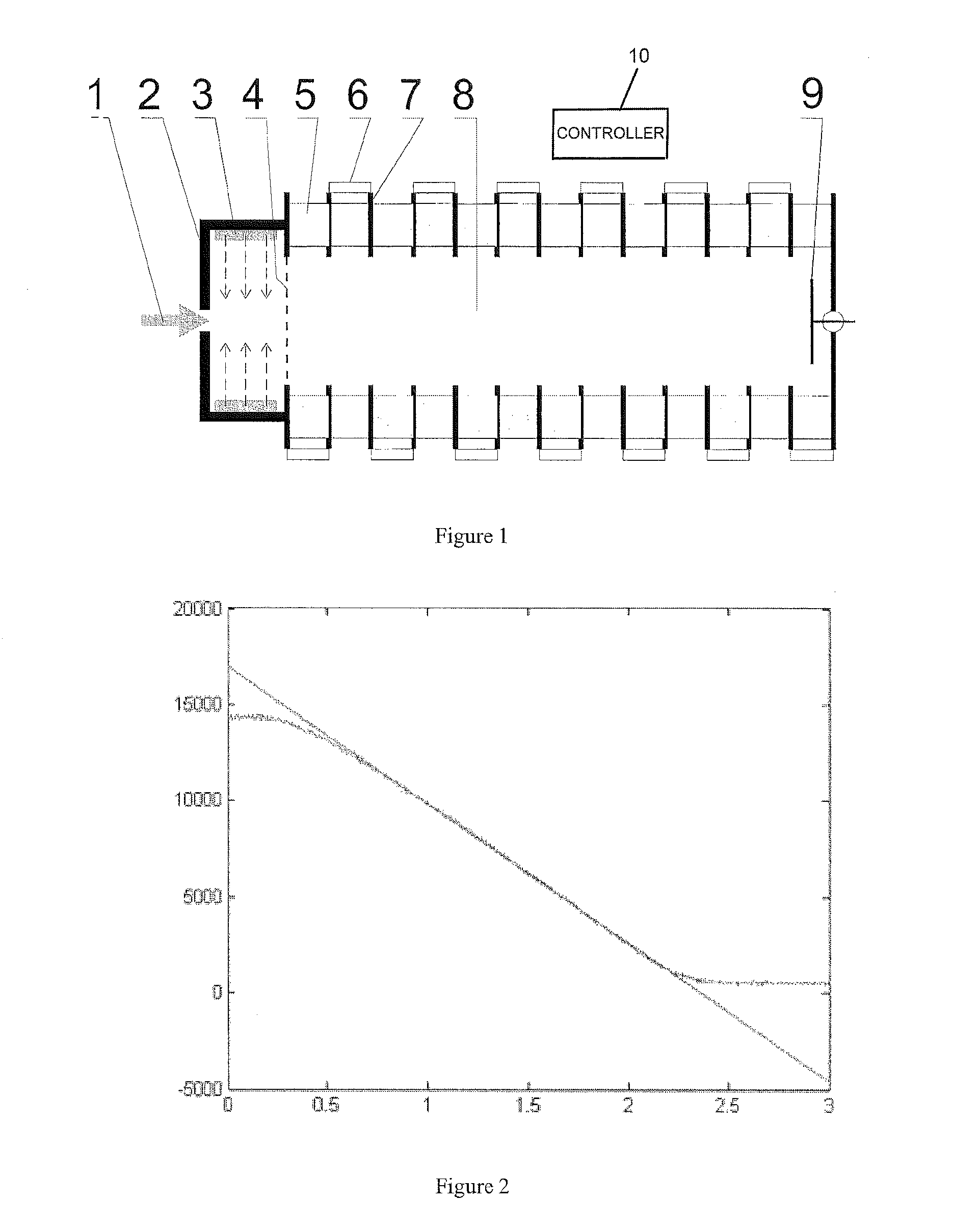
[0023]As can be seen from FIG. 2, the gating grid of a commercial ion mobility spectrometer may be used for the analog modulation; it even creates fewer problems than the operation with fast switching on and off that is required for a square-wave modulation. The analog modulation may be defined as “continuous” if the voltage increase or decrease is less than one volt per hundred microseconds.
[0026]The mobility spectrum thus obtained is a smooth curve with a high mobility resolution that can only be obtained by the conventional pulse method using very narrow pulse widths of less than one hundred microseconds. But the pulse method produces strong noise on the peaks of the mobility spectrum, particularly with such narrow pulse widths, which is not the case with the modulation method according to the invention. The signal-to-noise ratio is improved by a factor of five at roughly the same mobility resolution; this also improves the detection sensitivity by a factor of five.

Problems solved by technology

There are, however, major differences, which mainly concern the diffusion of the ions in the collision gas and thus the shape of the ion signals at the detector.
However, expectations for this method in terms of increasing the signal-to-noise ratio have been disappointing, and the method has not gained acceptance up to now.
It has become apparent, however, that this evaluation procedure using the Fourier transformation does not operate stably for a noisy detector signal.

Method used


Image

  • Measurement of ion mobility spectra
  • Measurement of ion mobility spectra
  • Measurement of ion mobility spectra

Examples


Embodiment Construction

[0032]Referring to FIG. 1, a system of the present invention analog-modulates the ion current from the ion source with a continuous modulation function with an instantaneous frequency varying over a wide frequency range, and decodes the resulting ion current signal at the detector by a correlation with the modulation function. This results in a relatively noise-free mobility spectrum with good mobility resolution. The modulation function may be a linear or nonlinear chirp. The evaluation procedure is extraordinarily stable.

[0033]This type of modulation (from the Latin “modulari”—to measure, control, regulate) differs from the modulation familiar from communications technology, which is used to modulate the amplitude, frequency or (more rarely) phase of a generally high-frequency carrier signal with a transported signal. The signal is then contained in the amplitude changes, in the frequency changes or (usually for digital signals only) in the phase shifts of the high-frequency carri...


PUM


Abstract

The invention relates to measuring the mobility spectra of ions with ion mobility spectrometers (IMS). The invention provides an analog modulation of the ion current of an IMS ion source with a continuous modulation function, the instantaneous frequency of which temporally varies across a large frequency range, and a generation of the mobility spectrum from the measured ion current by a correlation analysis with the modulation pattern. The modulation can, for example, be produced by the gating grid, which is usually present. The analog modulation removes many of the difficulties which occur with square-wave modulation and leads to a surprisingly stable evaluation which is relatively insensitive to noisy signals and produces a high mobility resolution at very low noise.

Description

PRIORITY INFORMATION[0001]This patent application claims priority from German patent application 10 2008 015 000.2 filed Mar. 19, 2008, which is hereby incorporated by reference.FIELD OF THE INVENTION[0002]The present invention relates to the field of ion mobility spectrometry and in particular to a method for measuring the mobility spectra of ions with an ion mobility spectrometer (IMS).BACKGROUND OF THE INVENTION[0003]Ion mobility spectrometers are usually operated by injecting short ion current pulses into the drift tube. The ions are continuously generated in an ion source and then admitted into the drift region of the spectrometer by a gating grid over a short time span. The time spans for the admission usually amount to between 100 and 300 microseconds; the acquisition of the spectrum takes about 30 milliseconds. Bipolar grids are used as gating grids.[0004]The ions admitted by the grid are drawn through a collision gas in a drift region by an axial electric field. The velocit...

Claims


Application Information

Patent Timeline
Patent Type & Authority Patents(United States)
IPC IPC(8): B01D59/44
CPCG01N27/622G01N27/64H01J49/04H01J49/06H01J49/10H01J49/40
Inventor RENNER, UWE
Owner BRUKER OPTICS GMBH & CO KG
Learn More