
Apparatus for detecting positions of wheels of vehicle and apparatus for detecting tire inflation pressure using the same

a technology for detecting the position of the wheels of the vehicle and the apparatus for detecting the inflation pressure of the tire, which is applied in the direction of tire measurement, vehicle components, transportation and packaging, etc. it can solve the problems of the receiver not being notified, the transceiver located farther from the triggering device cannot receive the triggering signal at all, and the resistance of the apparatus is increased. , to achieve the effect of preventing the apparatus and raising the resistance against stronger nois

Inactive Publication Date: 2009-01-15
DENSO CORP
View PDF3 Cites 8 Cited by
  • Summary
  • Abstract
  • Description
  • Claims
  • Application Information

AI Technical Summary

Benefits of technology

[0011]The present invention has been made in consideration of the foregoing difficulty, and an object of the present invention is to raise resistance against stronger noise by preventing the apparatus from erroneously determining system malfunctions in cases where there is no actual system malfunction.
[0013]Accordingly, when no reply can obtained from the transceivers in response to transmitting the triggering signal, the strength of noise surrounding each transceiver is measured. This noise measurement makes it possible that examine the reason why there is no reply from the transceivers. That is, it is possible check whether the reasons is due to either strong noise continuously surrounding the transceivers or system malfunctions such as a malfunction occurring in the hardware and / or software of a transceiver or a battery shutoff. Hence it is possible to avoid the erroneous determination that a system malfunction occurs although the system is practically in its normal state.

Problems solved by technology

However, in such a configuration, when the triggering signal is lower in strength than noise, each transceiver cannot receive the triggering signal in good order.
In particular, when the noise strength is higher, there is a risk that a transceiver located farther from the triggering device cannot receive the triggering signal at all.
In such a case, the transceiver cannot notify the receiver of the data showing the strength of the triggering signal.
However, the above alarming system is still confronted with a difficulty.
Nonetheless, the apparatus erroneously determines a system malfunction occurring in the apparatus and outputs an alarm, which results in issuing an error alarm.

Method used


Image

  • Apparatus for detecting positions of wheels of vehicle and apparatus for detecting tire inflation pressure using the same
  • Apparatus for detecting positions of wheels of vehicle and apparatus for detecting tire inflation pressure using the same
  • Apparatus for detecting positions of wheels of vehicle and apparatus for detecting tire inflation pressure using the same

Examples


first embodiment

[0025]Referring to FIGS. 1-5, a first embodiment will now be described.

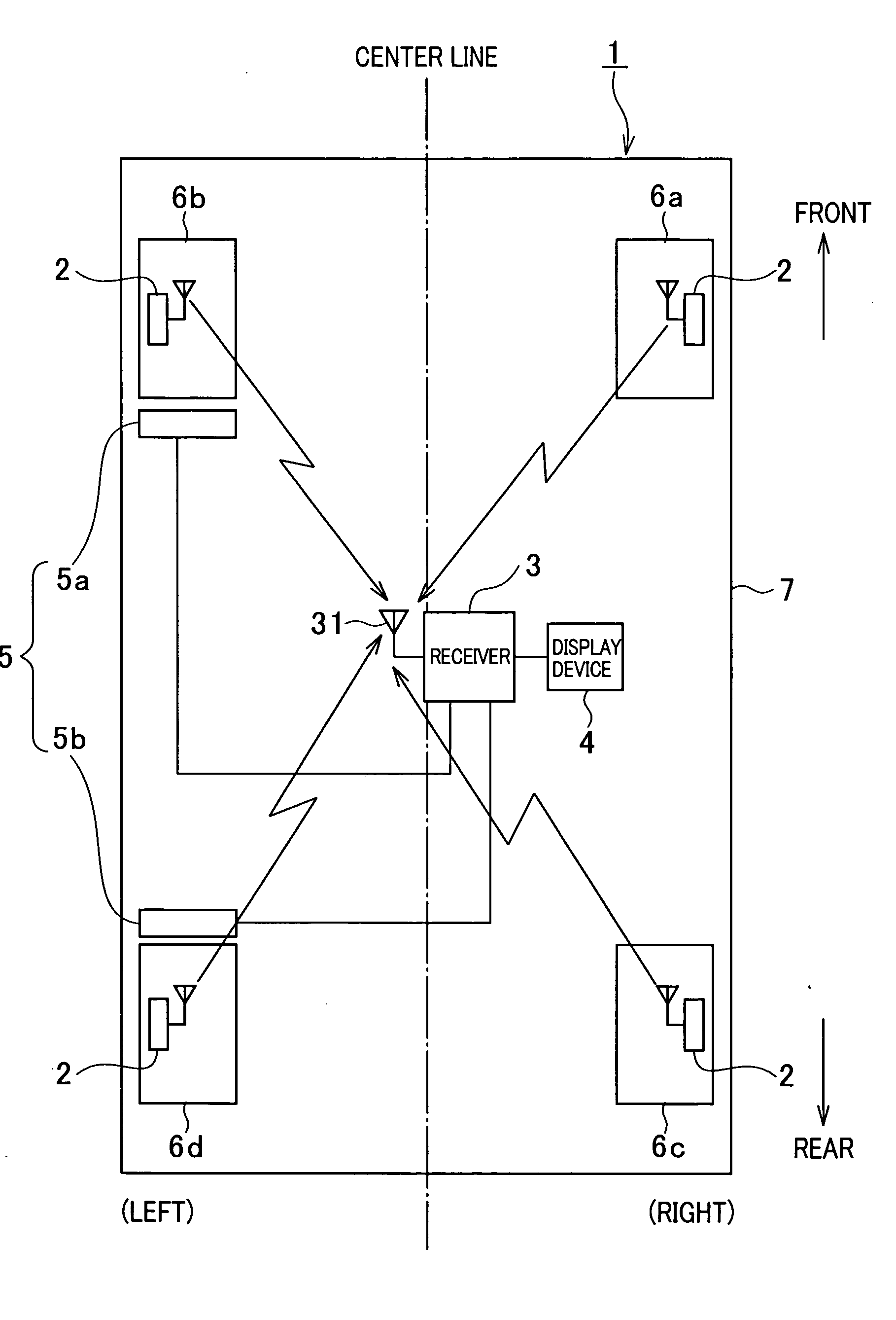
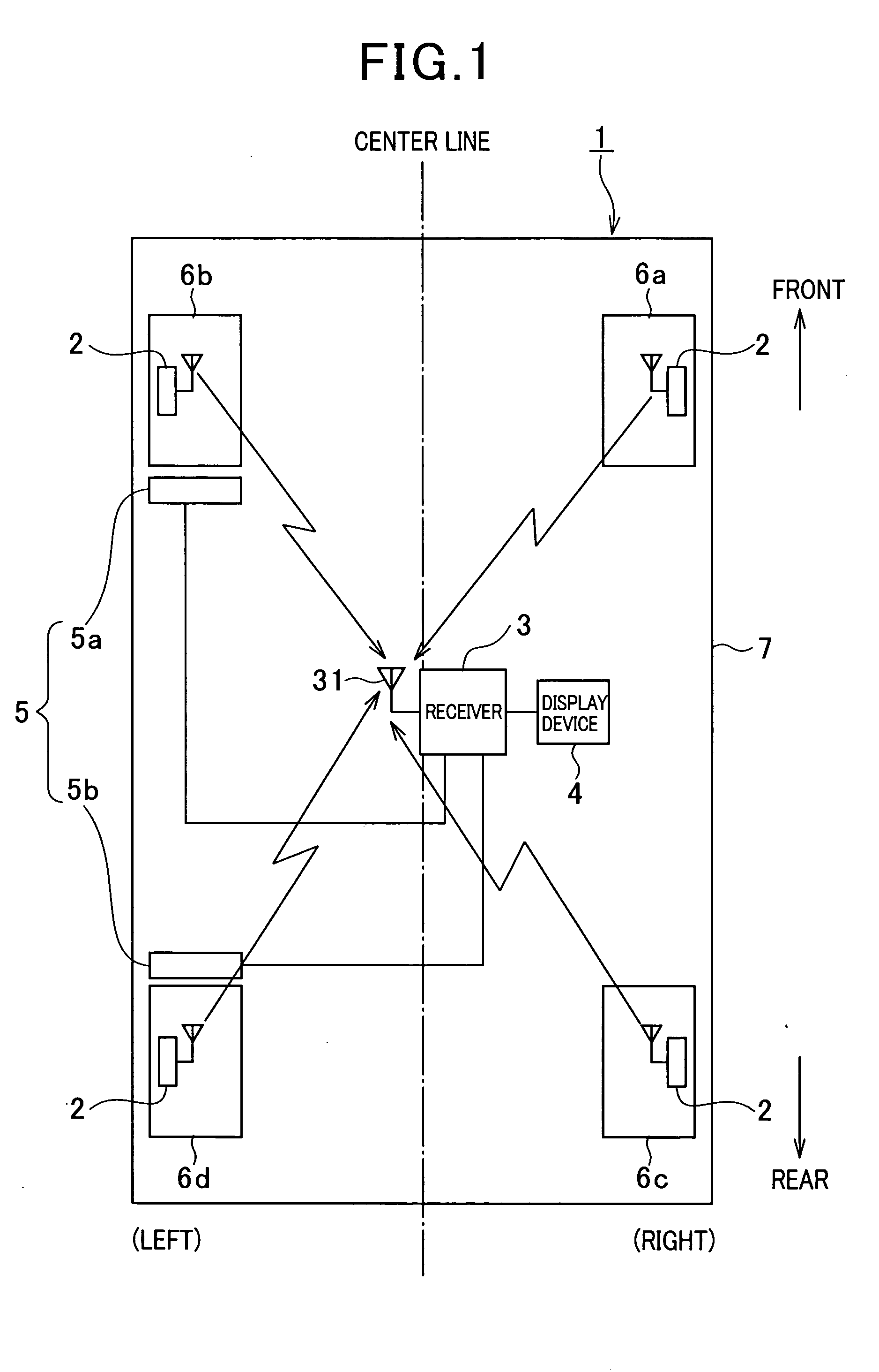
[0026]FIG. 1 shows the overall configuration of a tire inflation pressure detecting apparatus to which the wheel position detecting apparatus according to the first embodiment of the present invention is functionally applied.

[0027]The tire inflation pressure detecting apparatus is installed to a vehicle 1 and configured to detect the inflation pressure of four tires each of which is fitted to one of four wheels 6a-6d of the vehicle 1 (i.e., the front right (FR) wheel 6a, the front left (FL) wheel 6b, the rear right (RR) wheel 6c, and the rear left (RL) wheel 6d) or one of five wheels including a spare tire.

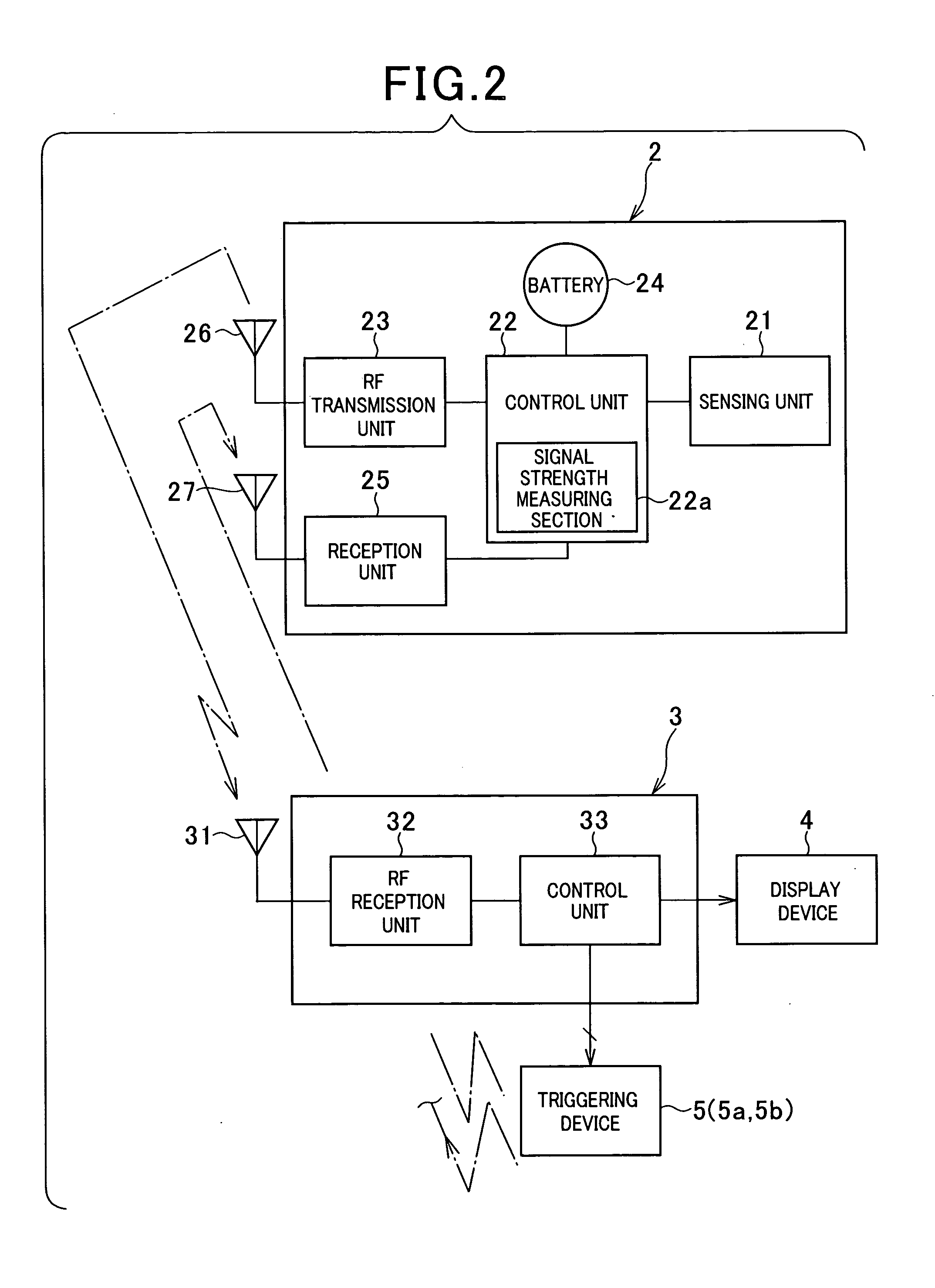
[0028]As shown in FIG. 1, the tire inflation pressure detecting apparatus, which is or is to be mounted on a vehicle 1, includes four transceivers 2, a receiver 3, a display device 4, and triggering devices 5 (5a and 5b). In the present embodiment, the transceivers 2, receiver 3, display device 4r and trigging ...

second embodiment

[0093]Referring to FIG. 6, a tire inflation pressure detecting apparatus according to a second embodiment of the present invention will now be described.

[0094]In the second embodiment, the identical or similar components to those in the first embodiment will be given the same reference numbers for the sake of simplified of omitted description.

[0095]The tire inflation pressure detecting apparatus according to the second embodiment is characteristic of performing a preliminary noise strength measurement before the wheel position detection, while in the first embodiment, the noise strength measurement is performed in only cases when there is no response from two transceivers.

[0096]Though the basic hardware and / or software configurations of the tire inflation pressure detecting apparatus are the same as those explained in the first embodiment, but differ from those in the first embodiment in the noise strength measurement executed by the control unit 33 of the receiver 3.

[0097]FIG. 6 sh...


PUM


Abstract

An apparatus for detecting positions of wheels of a vehicle is provided. In the apparatus, a triggering signal is transmitted from the body side to each transceiver mounted at each wheel. In each transceiver, the strength of the received triggering signal is measured and formatted into a frame of data to be transmitted to a receiver mounted to the vehicle body. The strength of the triggering signal is used to detect wheel positions by determining that each transducer is disposed at which wheel. The receiver determines if there is a reply of the flame of data containing the strength when the triggering device transmits the triggering signal. When no replay comes from the transceiver, the strength of noise is measured in the transceiver in response to a command from the receiver. When the noise strength is less than a threshold, the receiver commands an alarm member to issue alarm.

Description

CROSS REFERENCES TO RELATED APPLICATION[0001]The present application relates to and incorporates by reference Japanese Patent application No. 2007-181963 filed on Jul. 11, 2007.BACKGROUND OF THE INVENTION[0002]1. Field of the Invention[0003]The present invention relates to an apparatus for detecting the positions of the wheels of a vehicle and an apparatus for detecting tire inflation pressure using such a vehicular wheel position detecting apparatus.[0004]2. Description of the Related Art[0005]One of known apparatuses for detecting inflation pressure of each tire of a vehicle is a direct detection type of apparatus for detecting the tire inflation pressure. This direct detection type of tire inflation pressure apparatus is provided with transceivers directly mounted to wheels to which tires are secured. The sensors are for example pressure sensors. In addition, an antenna and a receiver are provided in the vehicle body, so that the transceiver transmits, to the receiver via the ant...

Claims


Application Information

Patent Timeline
Patent Type & Authority Applications(United States)
IPC IPC(8): B60C23/00
CPCB60C23/045B60C23/0416B60C23/0442B60C23/0462
Inventor MORI, MASASHI
Owner DENSO CORP
Learn More