Portable telephone apparatus with camera

a telephone and camera technology, applied in the field of portable telephone apparatuses with cameras, can solve the problems of deteriorating reception sensitivity, radio communication adversely affected, extreme deterioration of reception sensitivity, etc., and achieve the effect of reducing the interference between the harmonic components generated by the camera and the receiving frequency band for radio communication

Active Publication Date: 2005-11-17
MAXELL HLDG LTD
View PDF5 Cites 43 Cited by
  • Summary
  • Abstract
  • Description
  • Claims
  • Application Information

AI Technical Summary

Benefits of technology

[0026] The object of this invention is to provide a portable telephone apparatus with camera in which the interference between the harmonic components generated from the camera and the receiving frequency band for radio communication can be reduced.
[0028] As a result, even in the case where the camera has a large radiation energy, the operating clock signal frequency of the camera can be determined in such a manner that the frequency of the harmonic components of the camera is not superposed on the receiving band. Thus, a compact, lightweight and inexpensive portable telephone apparatus with camera can be provided in which the interference with the receiving frequency band for conducting radio communication is reduced with a camera of high pixel density and high frame rate.
[0030] As a result, the control circuit controls the clock signal of the clock signal generating circuit in such a manner that the harmonic components of the clock signal frequency is not superposed on the channel for radio communication, based on the information on the channel for radio communication. Thus, the operating clock signal frequency of the camera is required to be changed by a lesser amount, thereby reducing the effect that the change in the operating clock signal frequency has on the image quality.
[0032] Thus, the operating clock signal frequency of the camera can be changed sufficiently based on the setting of the table stored in advance, and therefore processing load of the control circuit is reduced for an improved versatility.
[0034] As a result, the operating clock signal frequency of the camera can be changed without changing the reference clock signal of the control circuit, and therefore the circuit operated on the reference clock signal is prevented from being affected.
[0035] This invention provides a portable telephone apparatus with camera in which the interference between the harmonic components generated from the camera and the receiving frequency band for radio communication can be reduced.

Problems solved by technology

In the case where a harmonic component of the clock signal of the control CPU coincides with the radio communication frequency band, the receiving sensitivity would be deteriorated extremely or the radio communication would otherwise be adversely affected.
In the case where the channel D is used in compliance with an instruction of the radio base station, for example, the channel D is superposed on the frequency of 864 MHz which is a harmonic 27 times as high as the camera operating frequency fc of 32 MHz, and the resultant interference of the radiation noise of the harmonic component poses the problem of a deteriorated receiving sensitivity.
In the conventional electrical shielding method described in JP-A-6-301448, the modules and even the flexible circuit of the camera are required to be shielded and therefore a compact, lightweight shield case cannot be fabricated.
Further, the cost is increased by an amount corresponding to the shield case.
Thus, this conventional method is not suitable for the portable telephone apparatus.
The prior art described in JP-A-7-303079, on the other hand, in which the clock signal frequency of the control circuit such as a control CPU is selectively changed, fails to deal with the operating clock signal frequency of the camera.
In the application to the portable telephone apparatus with camera, therefore, the problem is posed that the interference cannot be reduced against the radiation noise of the harmonic components generated from the camera having a large radiation energy.

Method used


Image

  • Portable telephone apparatus with camera
  • Portable telephone apparatus with camera
  • Portable telephone apparatus with camera

Examples


Embodiment Construction

[0043] Embodiments of the invention are explained in detail below with reference to the accompanying drawings.

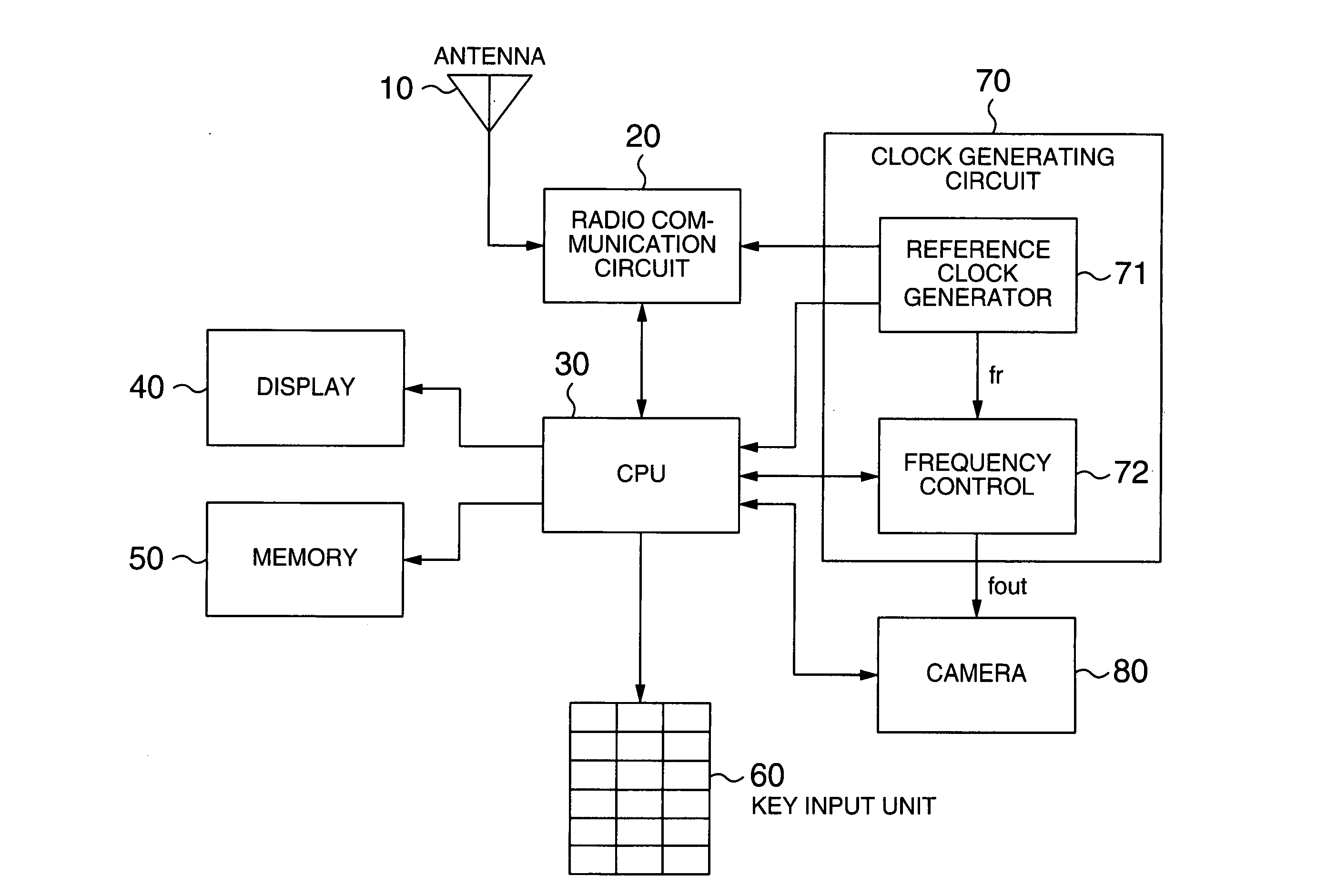
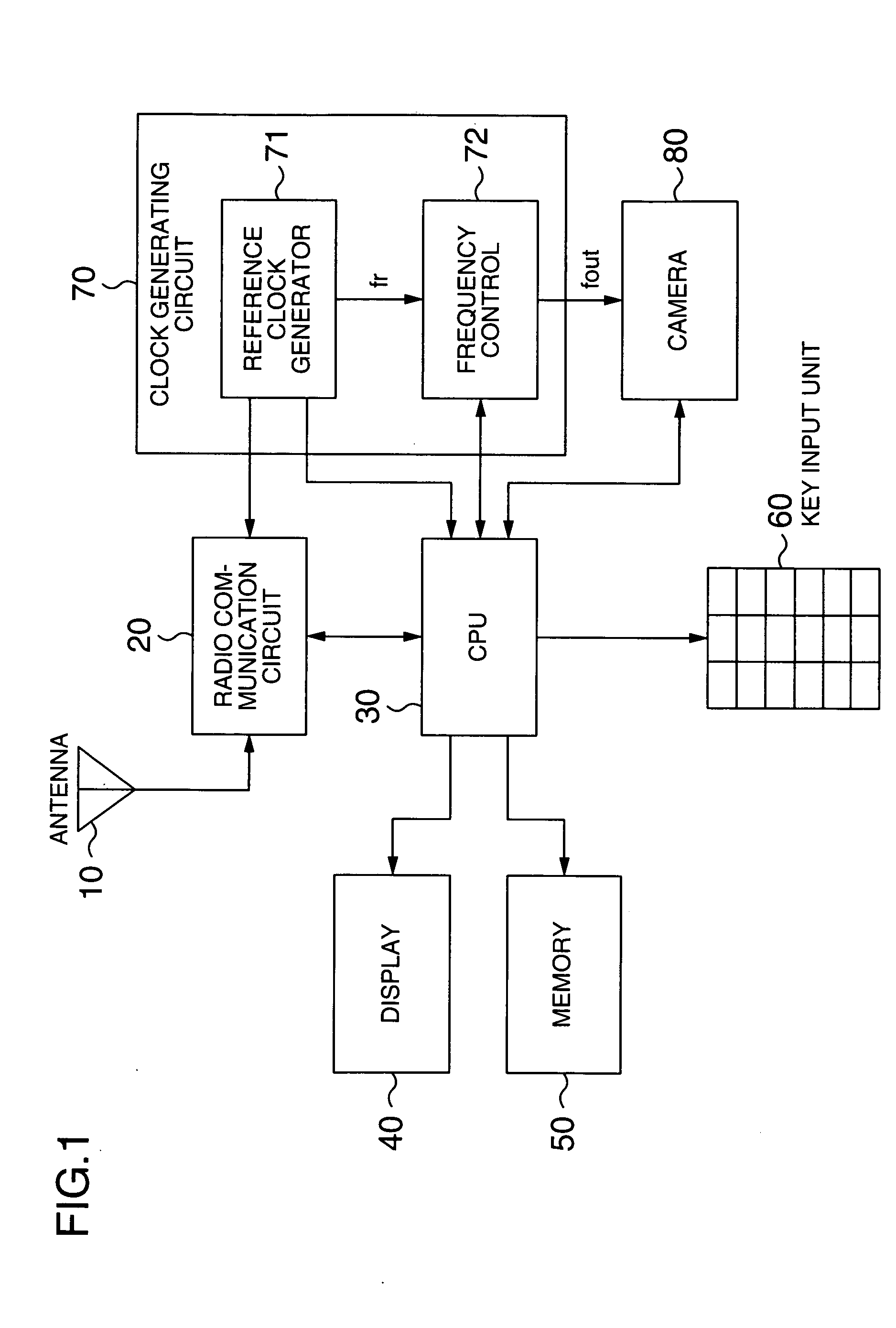
[0044]FIG. 1 is a block signal diagram showing a portable telephone apparatus with camera according to an embodiment of the invention. This portable telephone apparatus with camera comprises an antenna 10 and a radio communication circuit 20 connected to the antenna 10. The radio communication circuit 20 includes a codec circuit for a digital signal required for radio communication, a modem circuit, a communication radio wave transmission circuit and a receiving detection circuit, whereby the portable telephone apparatus according to this embodiment can conduct radio communication.

[0045] This portable telephone apparatus with camera comprises a CPU 30 for controlling the various functions as a portable telephone. The CPU 30 controls the radio communication circuit 20 and exchanges the transmission and receiving data with the radio communication circuit 20. As a result, the...


PUM


Abstract

A portable telephone apparatus with camera is disclosed, in which the interference between the harmonic component generated from the camera and the receiving frequency band for radio communication can be reduced. The apparatus comprises a radio communication circuit for conducting the radio communication with an external device, a clock signal generating circuit capable of controlling the output clock signal frequency, a camera operated with the output clock signal as an operating clock signal and a control circuit. The control circuit, based on the receiving frequency band information acquired from the radio communication circuit, controls the clock signal of the clock signal generating circuit in such a manner that the harmonic components of the clock signal frequency are not superposed on the receiving frequency band for conducting the radio communication.

Description

INCORPORATION BY REFERENCE [0001] The present application claims priority from Japanese application JP2004-145993 filed on May 17, 2004, the content of which is hereby incorporated by reference into this application. BACKGROUND OF THE INVENTION [0002] The present invention relates to a portable telephone apparatus with camera, or in particular to a technique for the camera operating clock signal against the receiving frequency band in which the radio communication is conducted by the portable telephone apparatus. [0003] The portable telephone apparatus includes a control circuit having a CPU (central processing unit) for controlling the whole system in addition to a radio circuit for conducting the radio communication. In recent years, the processing speed of the control CPU mounted on the portable telephone apparatus has been increased in keeping with the improved functions for games and mail. This has also increased the clock signal frequency for operation of the control CPU. [000...

Claims


Application Information

Patent Timeline
Patent Type & Authority Applications(United States)
IPC IPC(8): H04M1/00H04B15/04H04N1/00
CPCH04B15/02H04B15/04H04B2215/064H04N2101/00H04M2250/52H04N1/00281H04B2215/065
Inventor YAMAMOTO, SHINYAOFUCHI, KENMIMURA, MASAO
Owner MAXELL HLDG LTD
Why Eureka
Try Eureka