Check patentability & draft patents in minutes with Patsnap Eureka AI!

System and method for communicating the synchronization status of memory modules during initialization of the memory modules

a technology of memory modules and synchronization status, which is applied in the direction of memory address/allocation/relocation, instruments, digital computers, etc., can solve the problems of limiting the data bandwidth between the relatively slow speed of the memory controller and the memory device limits the data bandwidth of the processor and the memory device, and the design of the hub memory system

Active Publication Date: 2005-11-17
MICRON TECH INC
View PDF99 Cites 37 Cited by
  • Summary
  • Abstract
  • Description
  • Claims
  • Application Information

AI Technical Summary

Problems solved by technology

Although the operating speed of memory devices has continuously increased, this increase in operating speed has not kept pace with increases in the operating speed of processors.
The relatively slow speed of memory controllers and memory devices limits the data bandwidth between the processor and the memory devices.
Although there are advantages to utilizing a memory hub for accessing memory devices, the design of the hub memory system, and more generally, computer systems including such a memory hub architecture, becomes increasingly difficult.
In the case of timing skew of signals, it often arises from a variety of timing errors such as loading on the lines of the bus and the physical lengths of such lines.
As the size of signal eyes decrease at higher transfer rates, the variations in the location of the signal eyes become more of a problem.
However, in practice, even this approach becomes ineffective as signal transfer rates continue to decrease.
However, this technique adds a fair degree of complexity to the memory hubs 116 and is not always effective.

Method used


Image

  • System and method for communicating the synchronization status of memory modules during initialization of the memory modules
  • System and method for communicating the synchronization status of memory modules during initialization of the memory modules
  • System and method for communicating the synchronization status of memory modules during initialization of the memory modules

Examples


Embodiment Construction

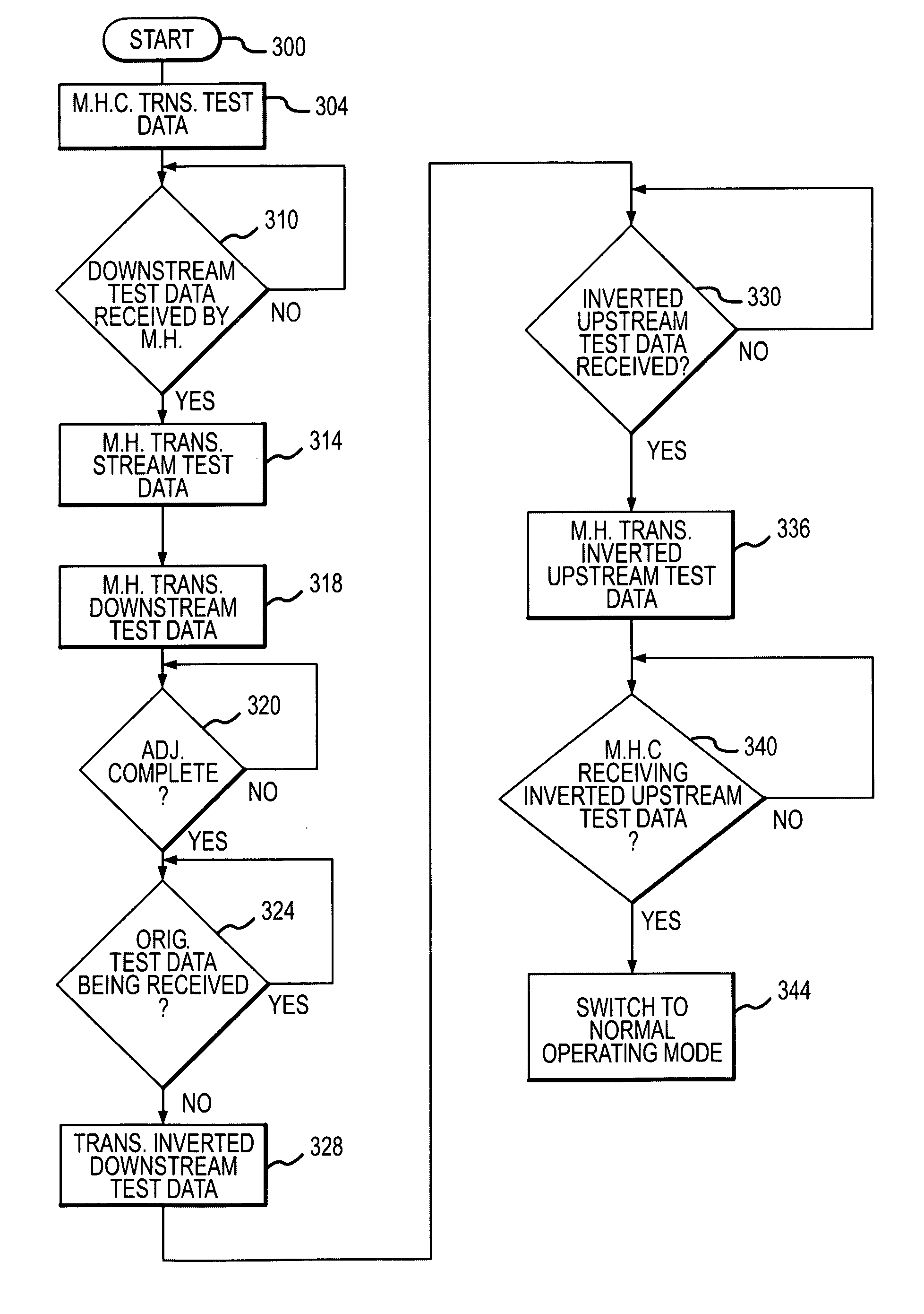
[0017] Embodiments of the present invention are directed to a memory module and memory hub controller each having the capability of generating a clock signal for strobing data signals during the “eye” of the data signals when the data signals are valid. More particularly, embodiments of the present invention are directed to a system and method for communicating the initialization status of the memory module and memory hub controller. Certain details are set forth below to provide a sufficient understanding of various embodiments of the invention. However, it will be clear to one skilled in the art that the invention may be practiced without these particular details. In other instances, well-known circuits, control signals, and timing protocols have not been shown in detail in order to avoid unnecessarily obscuring the invention.

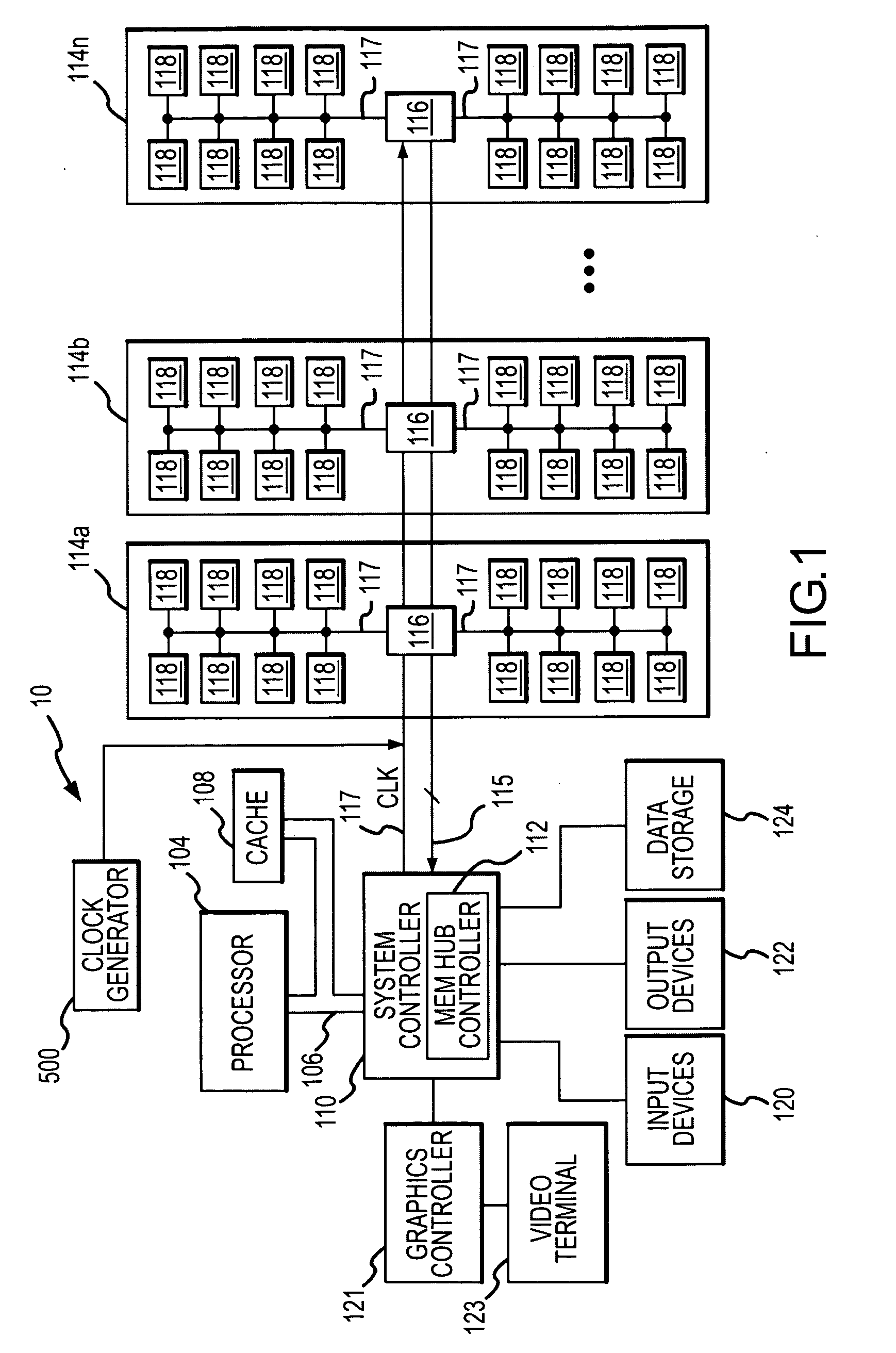
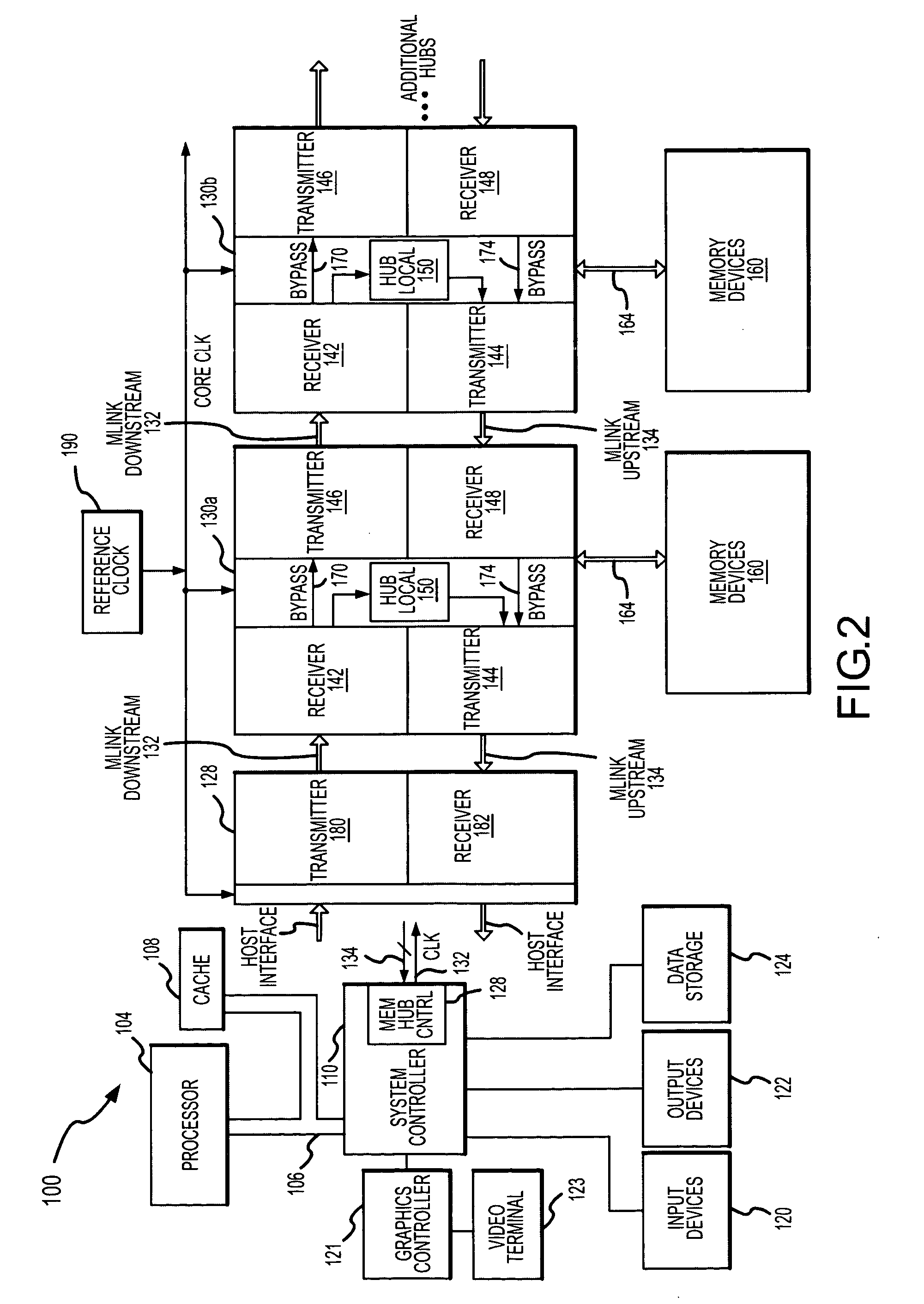
[0018] A computer system 100 having a hub memory system according to one embodiment of the invention is shown in FIG. 2. The computer system 100 uses many o...


PUM


Abstract

A memory system includes a memory hub controller coupled to a plurality of memory modules each of which includes a memory hub. The memory hub controller and the memory hubs each include at least one receiver that is synchronized to an internal clock signal during initialization. The memory hub controller and the memory hubs each transmit an initialization complete signal downstream when at least one receiver in the controller or hub is initialized and, in the case of the memory hubs, when a downstream initialization signal has also been received. Similarly, the memory hubs transmit an initialization signal upstream to another memory hub or the controller when both of its receivers are initialized and an upstream initialization signal has also been received. Receipt of an upstream initialization signal by the memory hub controller signifies that all of the receivers have been initialized.

Description

TECHNICAL FIELD [0001] The present invention relates to a processor-based system, and more particularly, to a processor-based system having a memory module with a memory hub coupling several memory devices to a processor or other memory access device. BACKGROUND OF THE INVENTION [0002] Processor-based systems, such as computer systems, use memory devices, such as dynamic random access memory (“DRAM”) devices, as system memory to store instructions and data that are accessed by a processor. In a typical computer system, the processor communicates with the system memory through a processor bus and a memory controller. The processor issues a memory request, which includes a memory command, such as a read command, and an address designating the location from which data or instructions are to be read or to which data or instructions are to be written. The memory controller uses the command and address to generate appropriate command signals as well as row and column addresses, which are ...

Claims


Application Information

Patent Timeline
IPC IPC(8): G06F12/00G06F13/16
CPCG06F13/1684
Inventor JAMES, RALPH
Owner MICRON TECH INC
Features
  • R&D
  • Intellectual Property
  • Life Sciences
  • Materials
  • Tech Scout
  • Unparalleled Data Quality
  • Higher Quality Content
  • 60% Fewer Hallucinations
Learn More