

Image data processing apparatus, image data processing method, program, and recording medium
a technology of image data and processing apparatus, applied in the field of image data processing apparatus, image data processing method, program and recording medium, can solve the problems of very small display area and significant difficulty in checking contents
- Summary
- Abstract
- Description
- Claims
- Application Information
AI Technical Summary
Benefits of technology
Problems solved by technology
Method used
Image

Examples
first embodiment
(1-1) First Embodiment
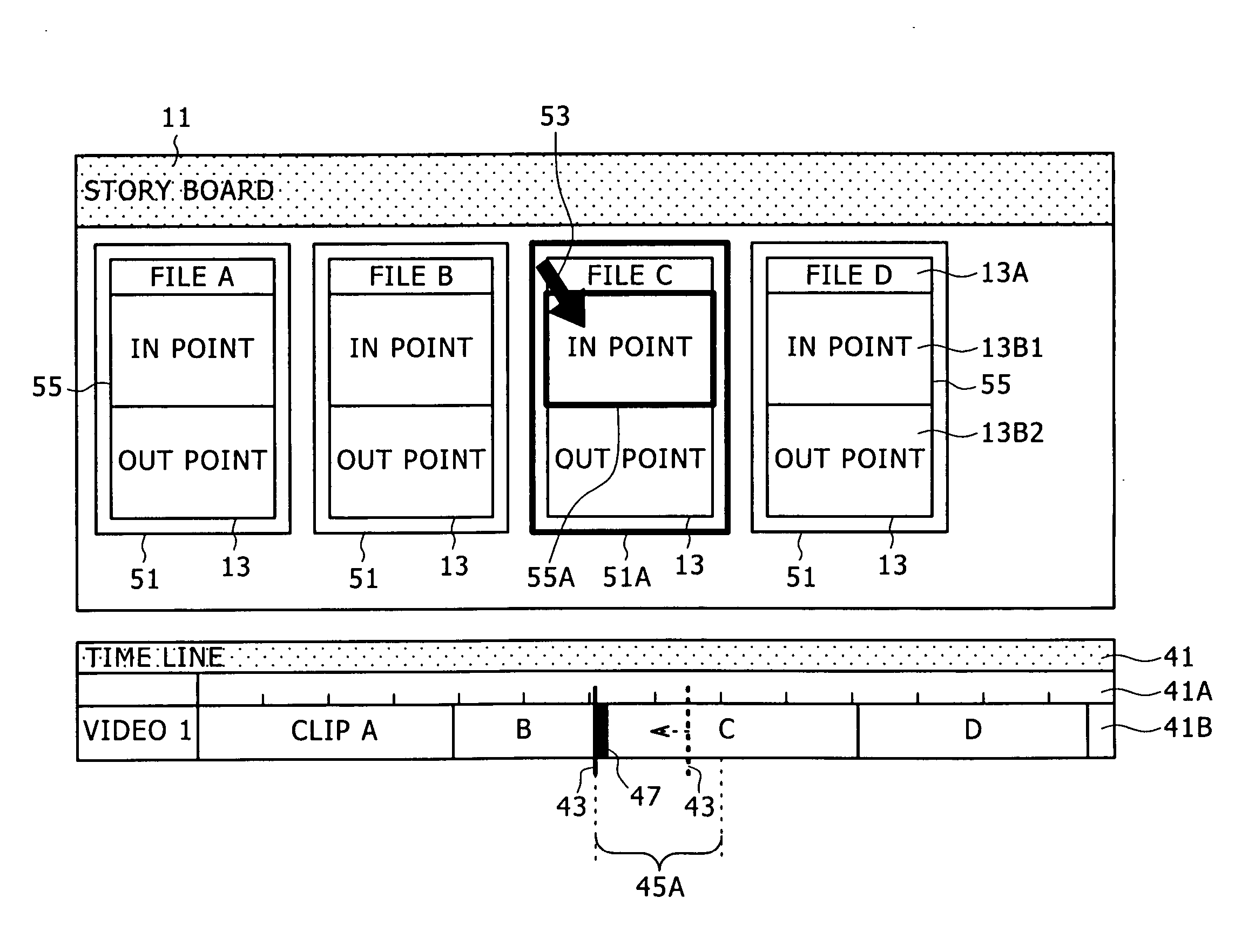
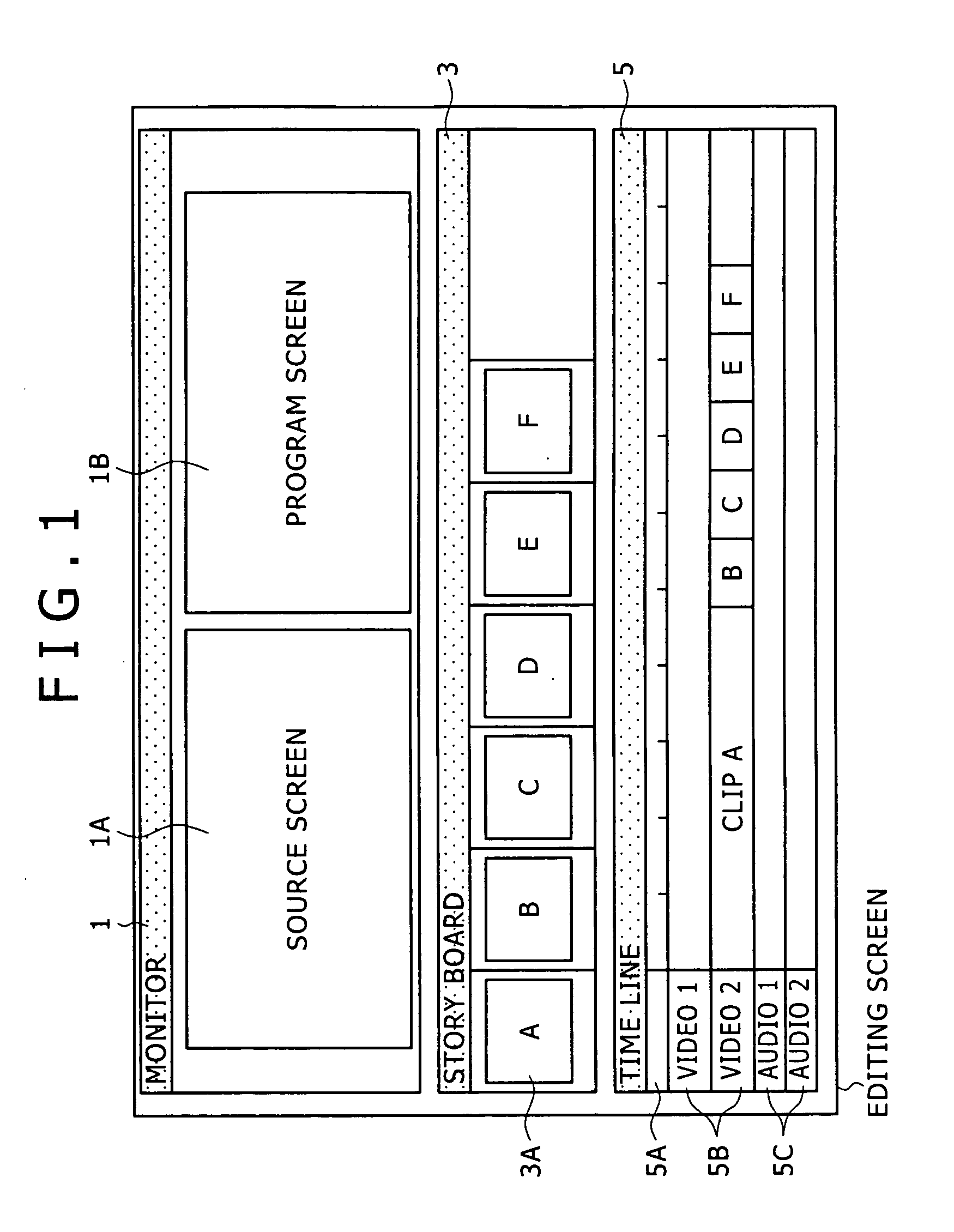
[0076]FIG. 3 shows an example of display of a story board window 11. FIG. 3 shows an example of display in which display areas 13 corresponding to respective clips are arranged in order of reproduction in the story board window 11. Incidentally, a direction of reproduction is from a left to a right.
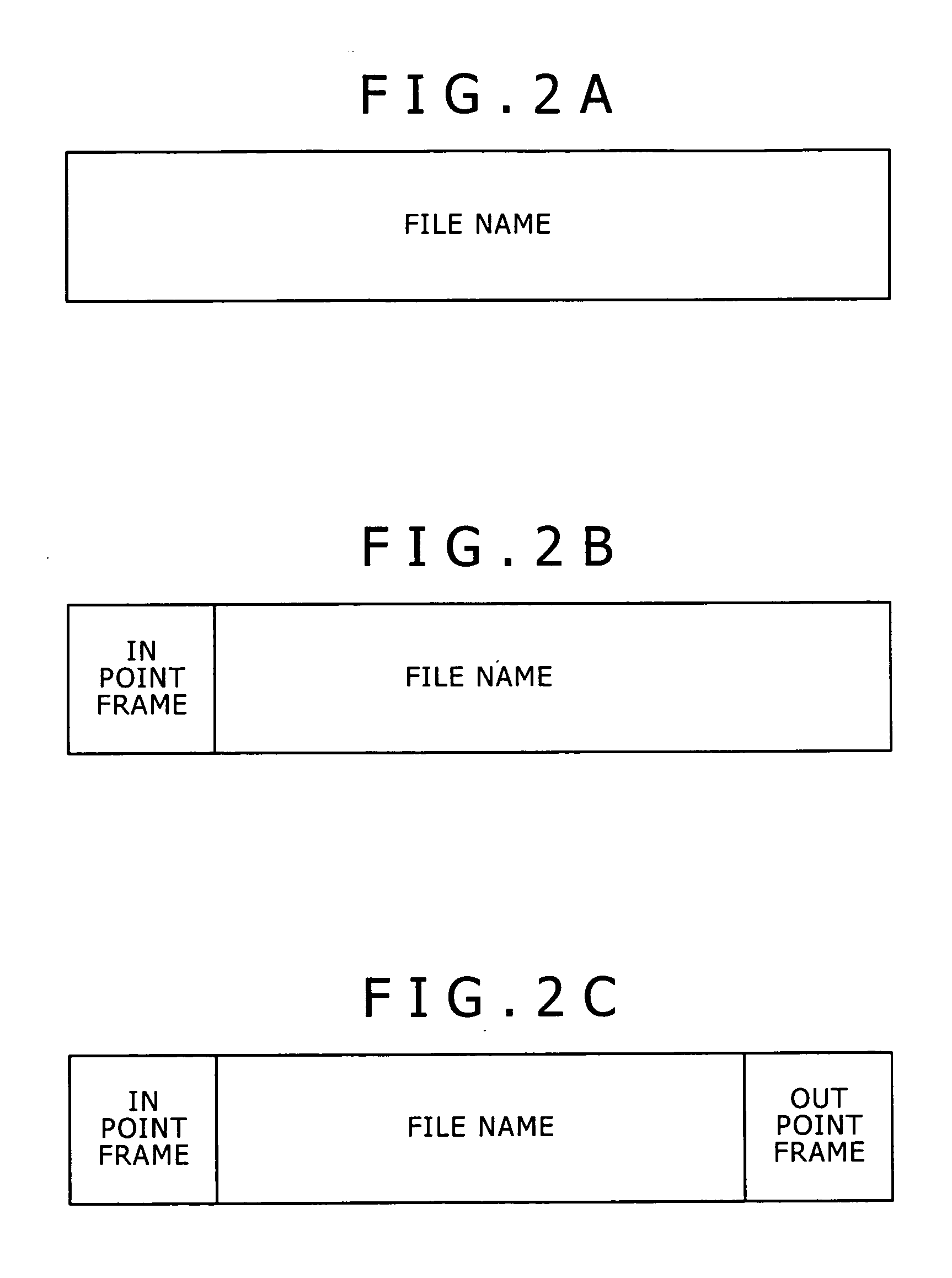
[0077] The three display areas 13 shown in FIG. 3 correspond to the clip A, the clip B, and the clip C, respectively. One display area 13 includes a title section (for example a file name) 13A and a thumbnail section 13B.
[0078] The thumbnail section 13B is an area for displaying thumbnail images at a plurality of points in time corresponding to each clip. Incidentally, a direction of reproduction is from a top to a bottom. For example, in the case of the thumbnail section 13B corresponding to the clip A, thumbnail images A2, A2 . . . AN are reproduced in that order.
[0079] The number of images displayed in the thumbnail section 13B can be given for each clip. In th...
second embodiment
(1-2) Second Embodiment
[0084] As described above, thumbnail images at a plurality of points in time forming each clip are displayed as one set in a thumbnail section 13B corresponding to each clip. In this embodiment, suppose that thumbnail images at a plurality of points in time specified arbitrarily by the user are displayed.
[0085]FIGS. 4A and 4B show an example of display in this case. FIGS. 4A and 4B show a case where the number of registered thumbnail images is two.
[0086]FIG. 4A shows an example of display of the thumbnail section 13B corresponding to the clip A. On the other hand, FIG. 4B shows positions (time point information) t1 and t2 within the clip to which thumbnail images A1 and A2 correspond.
[0087] For example, the positions in FIG. 4B represent frame positions at which an index mark recorded at a time of editing is set. Alternatively, for example, the positions in FIG. 4B represent frame positions at which an index mark recorded at a time of recording is set.
[008...
third embodiment
(1-3) Third Embodiment
[0094] In this embodiment, description will be made of a case where scene change points are automatically extracted as thumbnail images for display.
[0095]FIGS. 7A and 7B show an example of display in this case. FIGS. 7A and 7B show one clip formed by three sub-clips having no scene continuity therebetween. In image editing operations, short clips are often connected to each other to be handled as one clip. In this case, it is difficult to accurately grasp contents of the clip with a single thumbnail image.
[0096]FIG. 7A shows an example of display of the thumbnail section 13B corresponding to the clip A.
[0097] On the other hand, FIG. 7B shows positions (time point information) within the clip to which thumbnail images A1, A2, and A3 correspond. As shown in FIG. 7B, the thumbnail images A1, A2, and A3 correspond to in points of the respective sub-clips.
[0098] When such a display system is selected, all scene changes within the clip can be extracted. Incidenta...
PUM
| Property | Measurement | Unit |
|---|---|---|
| time | aaaaa | aaaaa |
| distance | aaaaa | aaaaa |
| area | aaaaa | aaaaa |
Abstract
Description
Claims
Application Information