Mems pilot valve

a pilot valve and valve body technology, applied in the field of valve devices, can solve the problems of inability to replace such units, limited correct operation of these devices, and inconvenient operation, and achieve the effect of increasing the tolerance to the presence of contamination

Inactive Publication Date: 2005-11-24
ABB RES LTD
View PDF6 Cites 22 Cited by
  • Summary
  • Abstract
  • Description
  • Claims
  • Application Information

AI Technical Summary

Benefits of technology

[0006] It is thus an object of the present invention to provide valves that

Problems solved by technology

Even though large pneumatic compressor based plants almost always are equipped with filter units in order to protect the equipment using the compressed air, and the equipment itself is also equipped with filter units, it is known that the correct operation these devices may often be limited by clogging of thin air channels by the deposition of films on surfaces exposed to the pressurised air.
Also, movable parts may permanently stick to other parts within the device and render a useless unit.
Such deposits build up

Method used


Image

  • Mems pilot valve
  • Mems pilot valve
  • Mems pilot valve

Examples


first embodiment

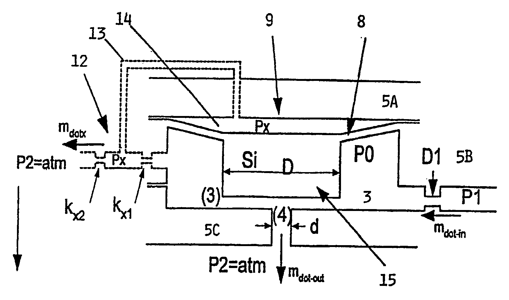
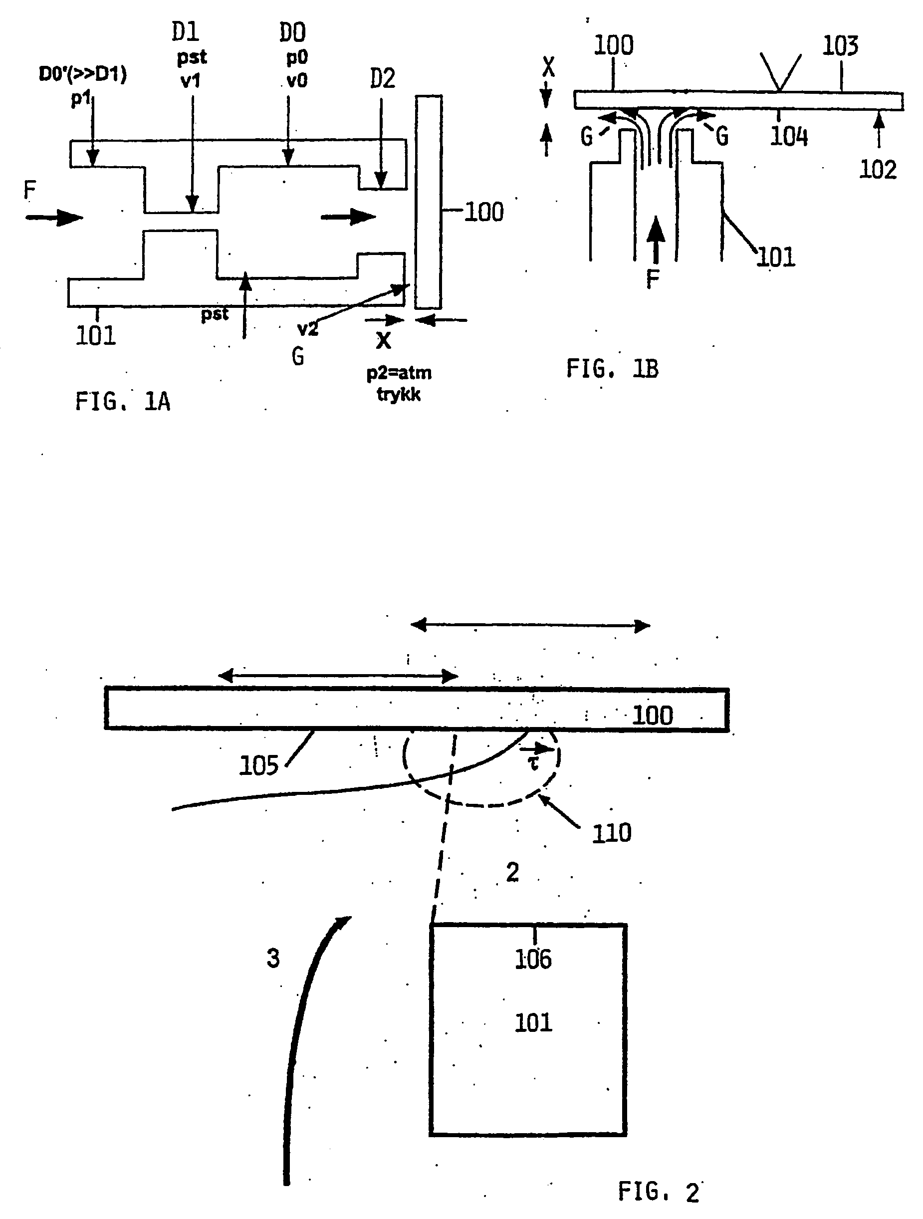
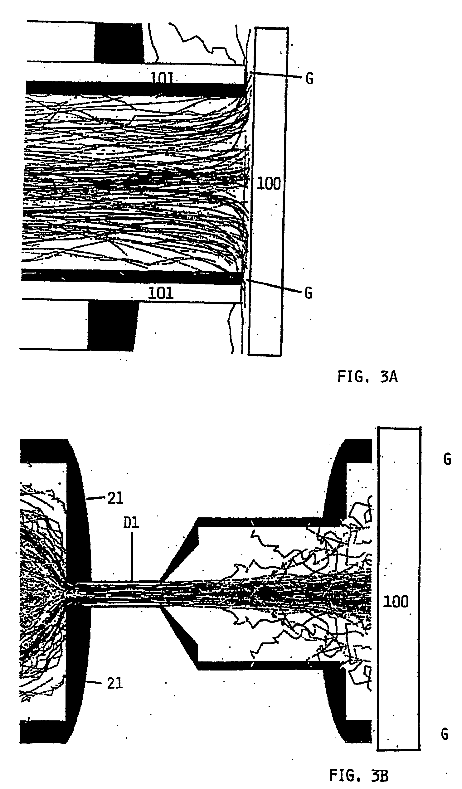
[0029] a MEMS-valve according to the invention, in particular for e.g. a pilot valve in an IP-regulator, is illustrated in FIG. 4. The valve comprises comprising a fluid inlet 3 and a fluid outlet 4 coupled by a fluid channel 2, all of which being defined by walls and structures 5 produced by micromachining of glass and or silicon. The valve also comprises an actuator 1,8,9 which can be set to at least at two different positions in order to vary the flow cross section of the fluid channel 2. The geometries of the fluid inlet, outlet and channel are adapted for preventing the flow from changing its direction so sharply that a significant portion of contaminating droplets and or particles in the flow hit the walls of structures, as given in any arrangement where the flow outlet and flow channel is generally parallel to flow inlet giving a substantially unidirectional flow pattern.

[0030] The fluid channel 2 couples the fluid inlet 3 and the fluid outlet 4. This embodiment of the invent...

second embodiment

[0039] In this second embodiment of the invention the fluid channel 2 has an actuator in the form of a bendable membrane 1, preferably micro-machined in silicon. The membrane 1 and the associated valve boss 15 can be forced to move, e.g. by an electrostatic, a thermal or piezo-electric actuator, thereby changing the internal cross section or cross sectional dimension of the fluid channel. By bending the silicon membrane the fluid channel cross section can be reduced in size, thereby providing a pressure drop between the fluid inlet 3 and fluid outlet 4. The actuator force is at least partly controlled by channel control means that are electrically connected to the actuator.

[0040] The structure and geometrical design of the MEMS-valve is adapted for high tolerance to impurities in the fluid supplied to the device in that the transverse dimension of the fluid outlet 4 is increased, depending on the density, size, and velocity of the particles or droplets in the flow, such that almost ...


PUM


Abstract

A valve including a fluid inlet and a fluid outlet coupled by a fluid channel, all of which are defined by walls and structures produced by micromachining of glass and/or silicon. An actuator can be set to at least two different positions in order to vary the flow cross section of the fluid channel. The geometries of the fluid inlet, outlet and channel are adapted for preventing the flow from changing its direction so sharply that a significant portion of contaminating droplets and or particles in the flow hit the walls of structures, as given in any arrangement according to or between the following two extremes: i) flow outlet is perpendicular to the flow inlet and the outlet dimension is larger than a critical dimension, Lcrit estimated according to a given formula and/or as simulated in a Computational Fluid Dynamics tool, and ii) flow outlet and flow channel is generally parallel to flow inlet giving a substantially unidirectional flow pattern.

Description

FIELD OF THE INVENTION [0001] This invention is related to a valve device, in particular miniature pilot valves, realised for example in a MEMS-structure (Micro Electro-Mechanical System). FIELD OF APPLICATION [0002] Pilot valves are typically used in pneumatic systems such as pneumatic production systems and are applied to control the pressure within large pneumatic actuators. Such actuators are used in processing equipment, for example in production processes where heavy machinery is moved or where large valves are controlled. [0003] Such pilot valves are often referred to as IP regulators, having an electrical (I for current) input and a pneumatic (P for pressure) output such that an analogue electrical signal generates a proportional corresponding pneumatic pressure at the output when the input is supplied with air from a supply unit, e.g. a compressor, with a largely constant high pressure. PRIOR ART [0004] Among a multitude of commercially available IP regulators is the TEIP 1...

Claims


Application Information

Patent Timeline
IPC IPC(8): F16K31/00F16K31/02
CPCF16K31/004F16K31/025F16K99/0001F16K2099/0076F16K99/0048F16K99/0051F16K99/0015Y10T137/7036Y10T137/7761
Inventor MIDTGARD, OLE-MORTENASSKILDT, KNUTNYSVEEN, ARNE
Owner ABB RES LTD
Why Eureka
Try Eureka