Casing running head

a running head and casing technology, applied in the direction of drilling pipes, drilling well accessories, sealing/packing, etc., can solve the problems of increasing the possibility of downtime, increasing the likelihood of thread damage, and time-consuming process of connecting and disconnecting the casing

Active Publication Date: 2005-11-24
WEATHERFORD TECH HLDG LLC
View PDF99 Cites 70 Cited by
  • Summary
  • Abstract
  • Description
  • Claims
  • Application Information

AI Technical Summary

Problems solved by technology

However, the process of connecting and disconnecting a casing is time consuming.
Furthermore, this process also increases the likelihood of damage to the threads, thereby increasing the potential for downtime.

Method used


Image

  • Casing running head
  • Casing running head
  • Casing running head

Examples


Embodiment Construction

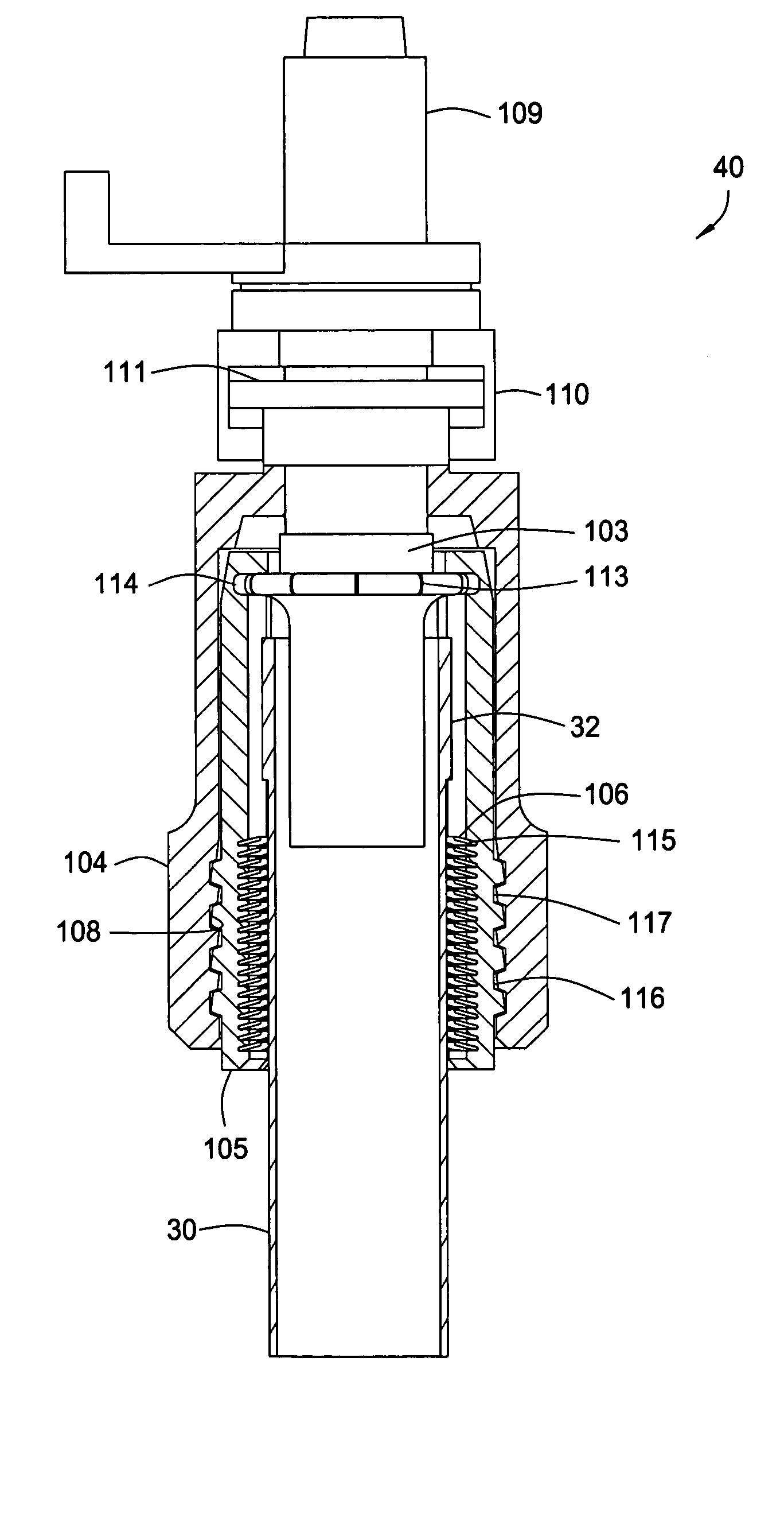
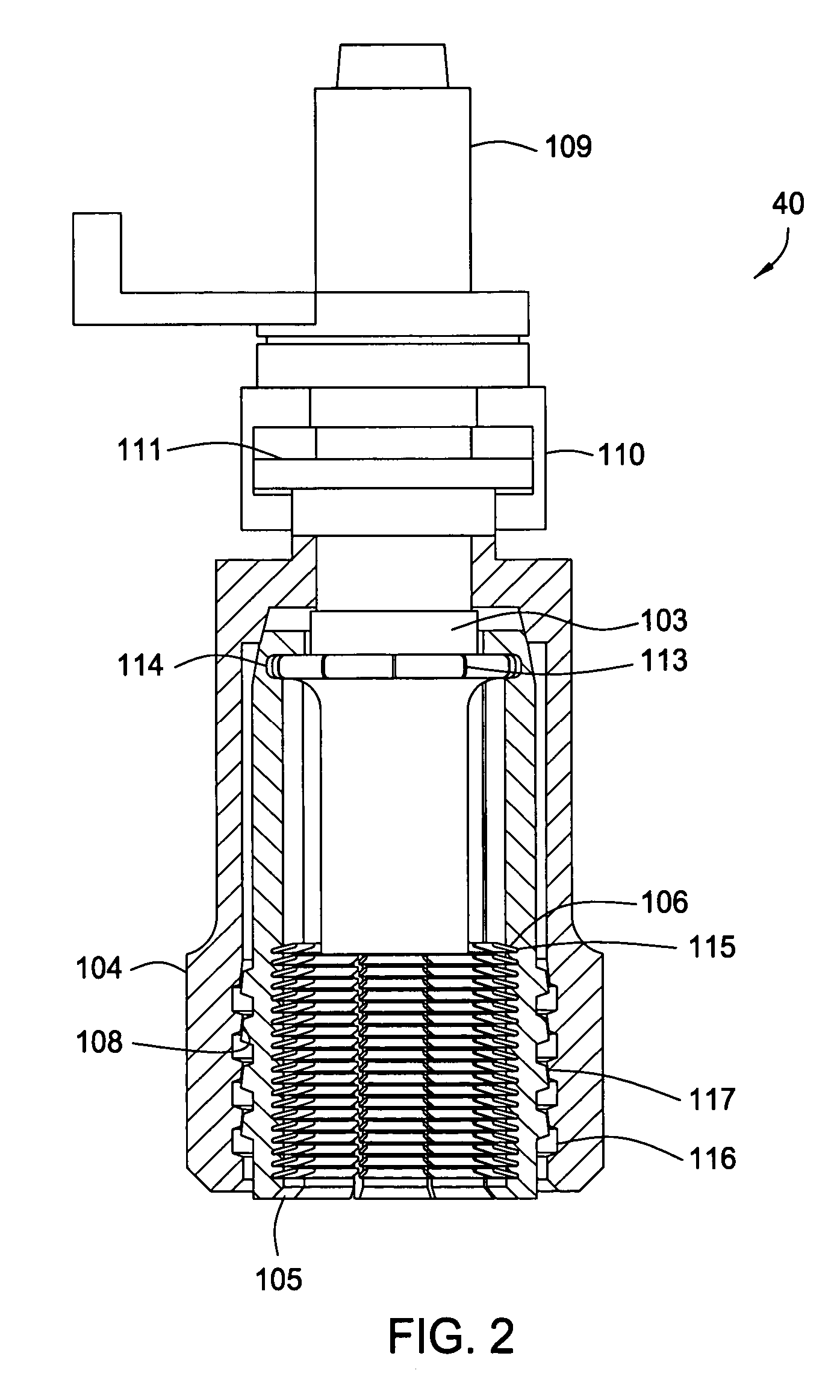
[0026] Aspects of the present invention provides a top drive adapter for gripping a casing for drilling with casing. The top drive adapter includes rotating unit for connection with the top drive to transfer torque. The top drive adapter also has a plurality of gripping elements disposed in a housing. Moving the housing axially relative to the plurality of gripping elements causes the gripping elements to apply an initial gripping pressure on the casing. The gripping elements have engagement members for contacting or gripping the casing. An axial load acting on the engagement members causes the engagement members to pivot axially and support the axial load.

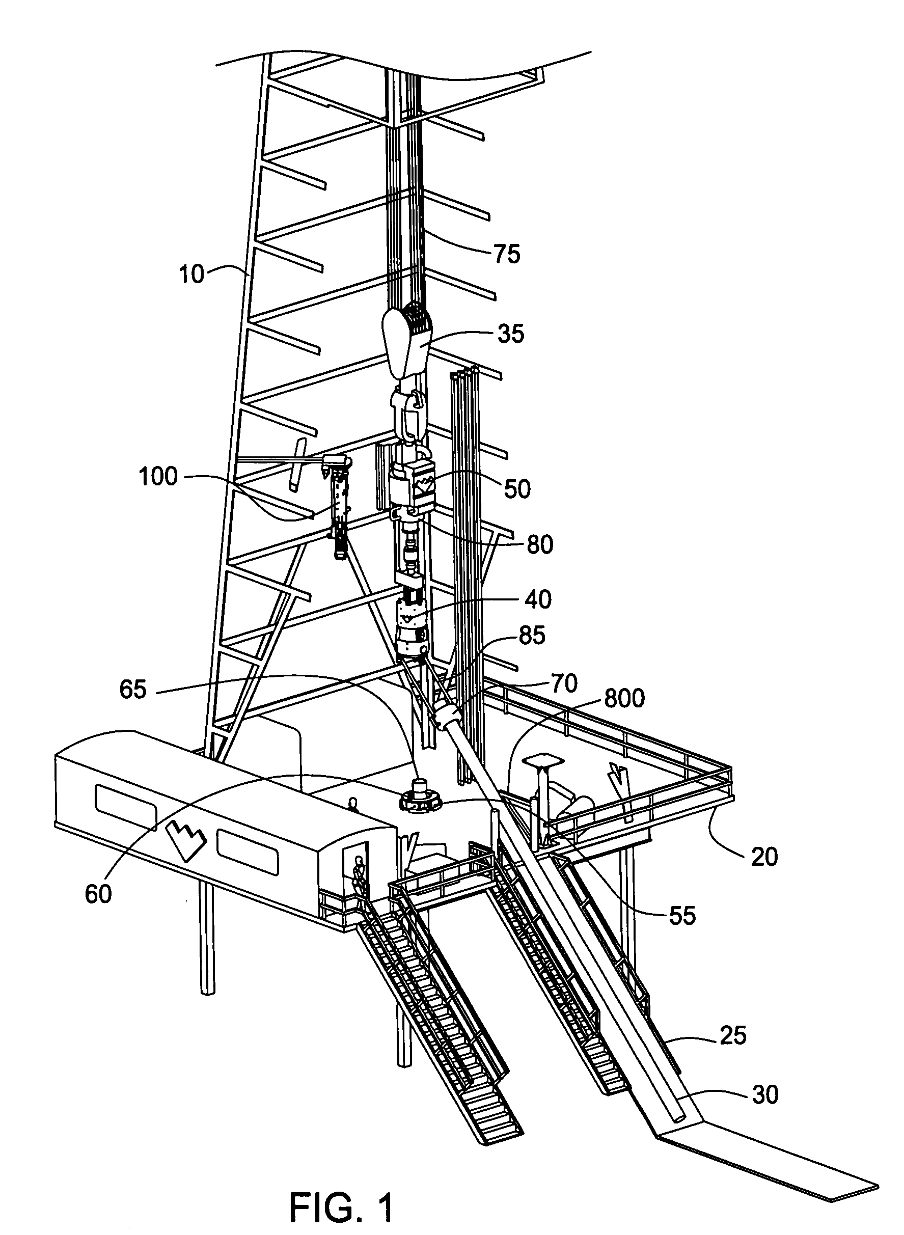
[0027]FIG. 1 shows a drilling rig 10 applicable to drilling with casing operations or a wellbore operation that involves picking up / laying down tubulars. The drilling rig 10 is located above a formation at a surface of a well. The drilling rig 10 includes a rig floor 20 and a v-door 800. The rig floor 20 has a hole 55 therethroug...


PUM


Abstract

The present invention generally relates to a method and apparatus for drilling with a top drive system. In one aspect, the present invention provides a tubular gripping member for use with a top drive to handle a tubular comprising a housing operatively connected to the top drive and a plurality of gripping elements radially disposed in the housing for engaging the tubular, wherein moving the housing relative the plurality of gripping elements causes the plurality of gripping members to engage the tubular.

Description

BACKGROUND OF THE INVENTION [0001] 1. Field of the Invention [0002] The present invention relates to methods and apparatus for drilling with top drive systems. Particularly, the invention relates to methods and apparatus for adapting a top drive for use with running casing. More particularly still, the invention relates to a torque head for engaging with a tubular and rotating the same. [0003] 2. Description of the Related Art [0004] In well completion operations, a wellbore is formed to access hydrocarbon-bearing formations by the use of drilling. Drilling is accomplished by utilizing a drill bit that is mounted on the end of a drill support member, commonly known as a drill string. To drill within the wellbore to a predetermined depth, the drill string is often rotated by a top drive or rotary table on a surface platform or rig, or by a downhole motor mounted towards the lower end of the drill string. After drilling to a predetermined depth, the drill string and drill bit are remo...

Claims


Application Information

Patent Timeline
Patent Type & Authority Applications(United States)
IPC IPC(8): E21BE21B3/02E21B19/00E21B19/02E21B19/04E21B19/06E21B19/07E21B19/08E21B19/10E21B19/16
CPCE21B19/07E21B19/00
Inventor PIETRAS, BERND-GEORG
Owner WEATHERFORD TECH HLDG LLC
Why Eureka
Try Eureka