Electric power steering apparatus

Active Publication Date: 2005-11-24
NSK LTD +1
View PDF10 Cites 24 Cited by
  • Summary
  • Abstract
  • Description
  • Claims
  • Application Information

AI Technical Summary

Benefits of technology

[0024] An object of the present invention is to provide an electric power steering apparatus that has only a small shift in an engagement position between a worm wheel and

Problems solved by technology

This prevents normal engagement, and hence causes problems such as the generation of noise in the engagement part and the occurrence of wear in the gear tooth surface.
This increases the processing cost, but still the concentricity of the bearing holes is difficult to be maintained so that the swing of the worm wheel 051 becomes large.
This prevents normal engagement, and hence causes problems such as the generation of noise in the engagement part and the occurrence of wear in t

Method used


Image

  • Electric power steering apparatus
  • Electric power steering apparatus
  • Electric power steering apparatus

Examples


first embodiment

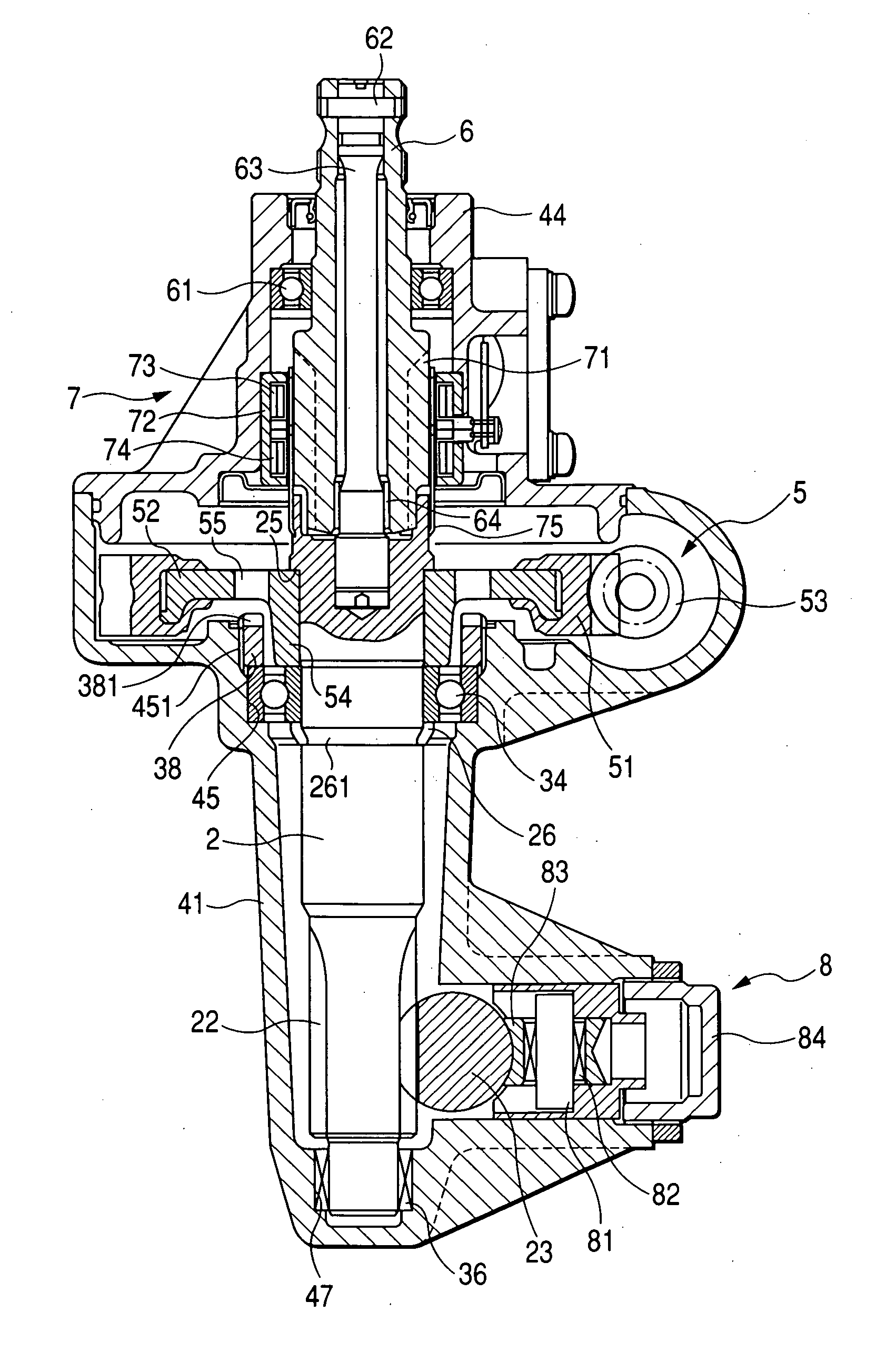
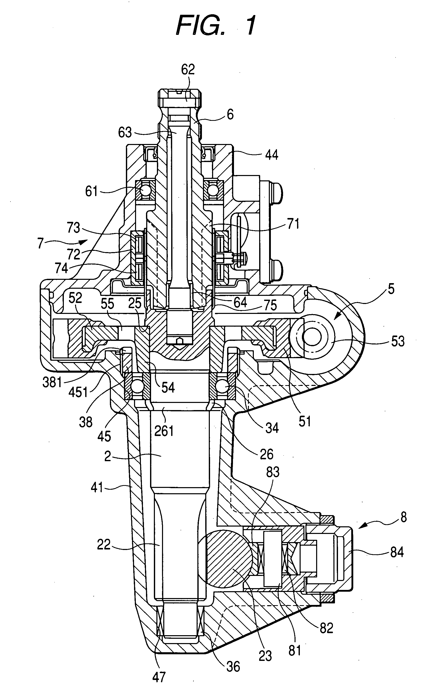
[0056] In this electric power steering apparatus 1 the ball bearing 34 serving as the support reference for the pinion shaft 2 is located directly under the worm wheel 51. Thus, even when a temperature change occurs around the electric power steering apparatus, the engagement position between the worm wheel 51 and the worm 53 shifts only slightly in the axial direction of the pinion shaft 2. This ensures normal engagement, and hence avoids the generation of noise in the engagement part and the occurrence of wear in the gear tooth surface.

[0057] Furthermore, the bearing hole 47 into which the outer race of the lower needle bearing 36 is pressed and the bearing hole 45 into which the outer race of the upper ball bearing 34 is pressed are formed in the same lower gear box 41. At the same time, these two holes can be fabricated using a boring tool by through processing from the bearing hole 45 side. This reduces the machining time, and yet improves the concentricity of the bearing hole...

second embodiment

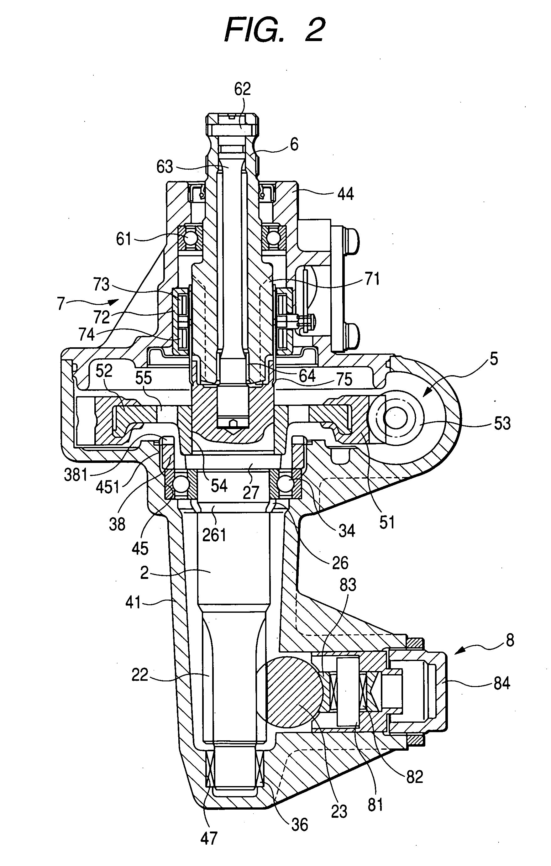
[0068] Also, in this electric power steering apparatus 1 the ball bearing 34 serving as the support reference for the pinion shaft 2 is located directly under the worm wheel 51. Thus, even when a temperature change occurs around the electric power steering apparatus, the engagement position between the worm wheel 51 and the worm 53 is always maintained in a normal engagement state.

[0069] A third embodiment of the invention is described below with reference to FIG. 3. Also, in the third embodiment, the fixing of the inner race of the ball bearing 34 to the pinion shaft 2 is performed by a different method from the first embodiment. In the following description, like parts to the first embodiment are designated by like numerals, and overlapping description is omitted.

[0070] In the first embodiment, the inner race of the ball bearing 34 has been fixed by the caulking ring 26 attached and caulked in the groove 261 of the pinion shaft 2. In the third embodiment, a nut 28 is screwed on ...

third embodiment

[0072] Also, in this electric power steering apparatus 1 the ball bearing 34 serving as the support reference for the pinion shaft 2 is located directly under the worm wheel 51. Thus, even when a temperature change occurs around the electric power steering apparatus, the engagement position between the worm wheel 51 and the worm 53 is always maintained in a normal engagement state.

[0073] A fourth embodiment of the invention is described below with reference to FIG. 4. Also, in the fourth embodiment, the fixing of the inner race of the ball bearing 34 to the pinion shaft 2 is performed by a different method from the first embodiment. In the following description, like parts to the first embodiment are designated by like numerals, and overlapping description is omitted.

[0074] In the first embodiment, the inner race of the ball bearing 34 has been fixed by the caulking ring 26 attached and caulked in the groove 261 of the pinion shaft 2. In the fourth embodiment, a retainer ring (sna...


PUM


Abstract

A ball bearing 34 serving as a support reference for a pinion shaft 2 is located directly under a worm wheel 51. Thus, even when a temperature change occurs around the electric power steering apparatus, the engagement position between the worm wheel 51 and the worm 53 shifts only slightly in the axial direction of the pinion shaft 2. Furthermore, a bearing hole 47 into which an outer race of a lower needle bearing 36 is pressed and a bearing hole 45 into which an outer race of an upper ball bearing 34 is pressed are formed in a common lower gear box 41, and can be fabricated by through processing using a boring tool from the bearing hole 45 side.

Description

BACKGROUND OF THE INVENTION [0001] The present invention relates to an electric power steering apparatus and, in particular, to an electric power steering apparatus capable of maintaining a good engagement state between a worm wheel and a worm. [0002] An example of a conventional electric power steering apparatus is shown in FIG. 8 where an electric power steering apparatus 01 has a supporting structure for a pinion shaft. The electric power steering apparatus 01 shown in FIG. 8 is an electric power steering apparatus of a pinion assist type. A lower end of a pinion shaft 02 is supported pivotally by a ball bearing 031 of a four-point contact type, while a lock nut 032 is screwed on a male screw 021 provided at the lower end of the pinion shaft 02. This lock nut 032 fixes the lower end of the pinion shaft 02 to an inner race of the ball bearing 031. [0003] An outer race of the ball bearing 031 is pressed into a bearing hole 042 formed in a lower gear box 041. The outer race of the b...

Claims


Application Information

Patent Timeline
IPC IPC(8): B62D3/12B62D5/04
CPCB62D3/123B62D3/126Y10T74/19842B62D5/0421B62D5/0409
Inventor ISHII, NOBUHIROUBUKATA, HISAO
Owner NSK LTD
Why Eureka
Try Eureka