
Retractable tether device for hand tools

Inactive Publication Date: 2005-11-24
WEAVER WILLIAM WESLEY
View PDF13 Cites 64 Cited by
  • Summary
  • Abstract
  • Description
  • Claims
  • Application Information

AI Technical Summary

Benefits of technology

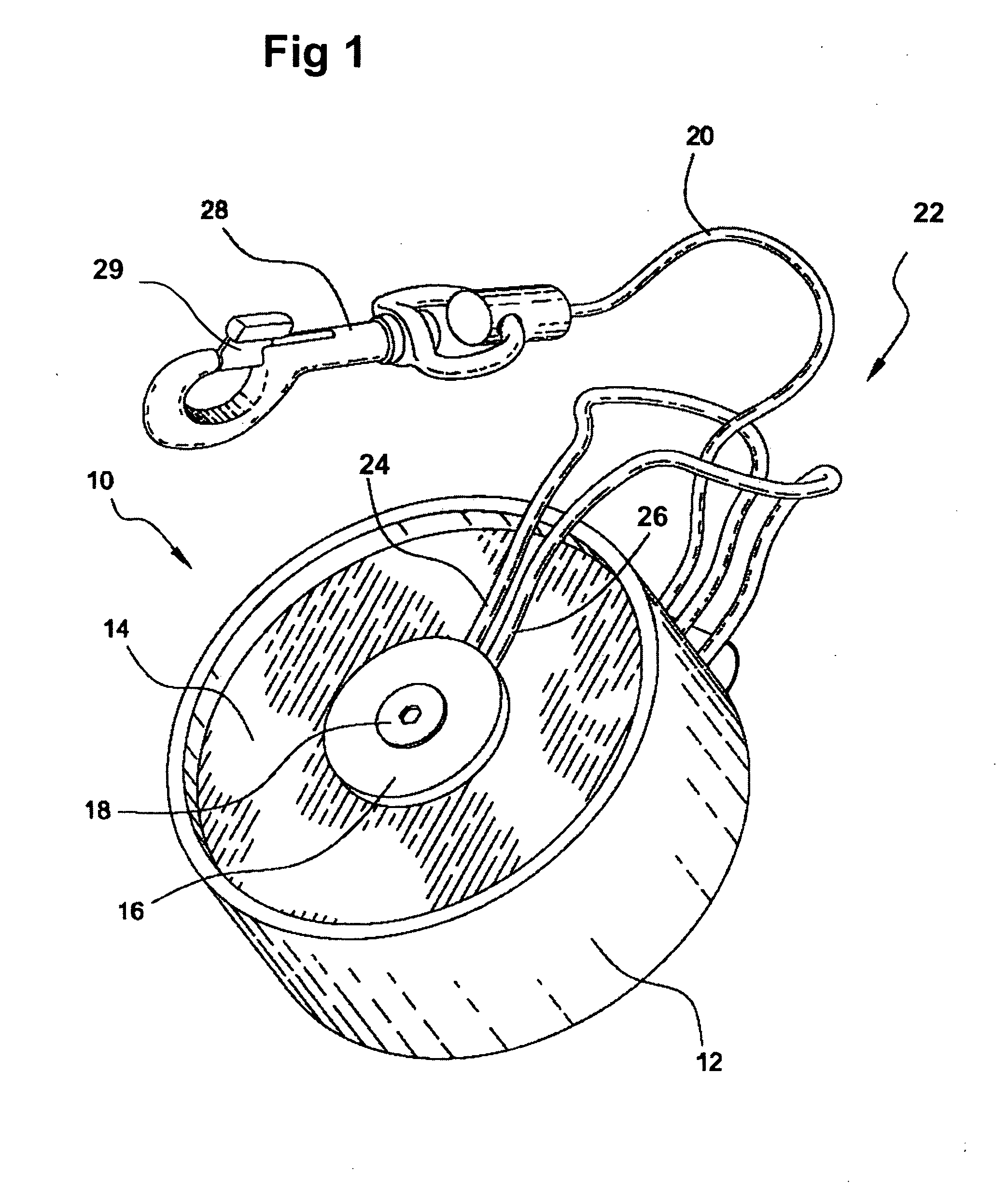
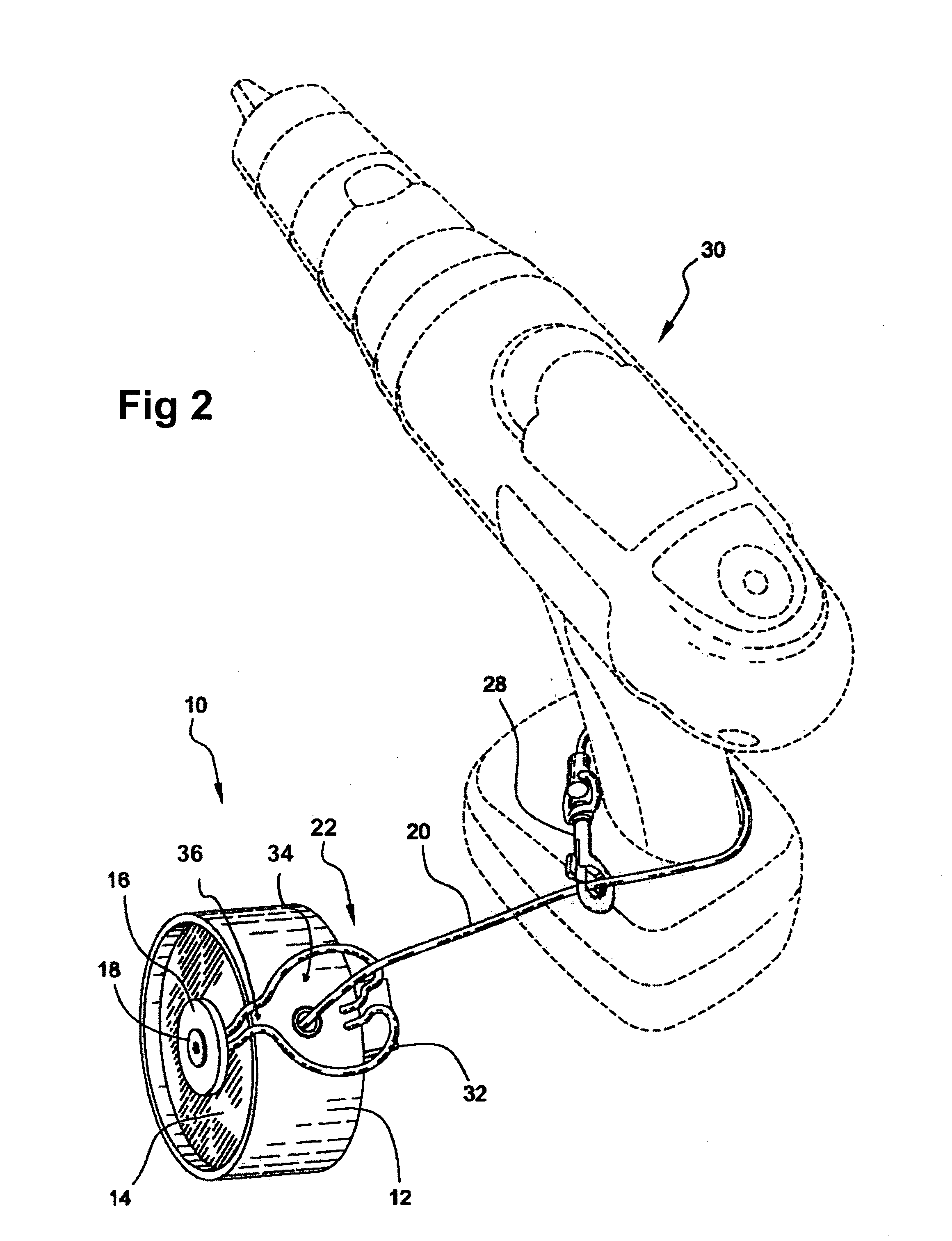
[0009] The cord is biased for automatic retraction and winding on the reel. In order to use the power tool attached to the cord, tension must be reduced in the cord so that the reel is not constantly trying to wind the cord and, therefore, the power tool back onto the reel. To that end, the present invention provides a cord retainer arrangement that is formed from two converging rail segments that are mounted to the housing. The cord may be wedged intermediate the rail segments for tension reduction on the cord.
[0010] To those ends, a retractable tether device for tools includes a housing and a reel disposed within the housing, the reel being biased for rotation in a rewinding dire

Problems solved by technology

This solution can be inadequate because a power drill in a shoulder holster can be cumbersome and although the tool remains supported, it is not restrained such that the user may drop the tool from the holster that instantly defeats the purpose of the holster.

Method used


Image

  • Retractable tether device for hand tools
  • Retractable tether device for hand tools
  • Retractable tether device for hand tools

Examples


Embodiment Construction

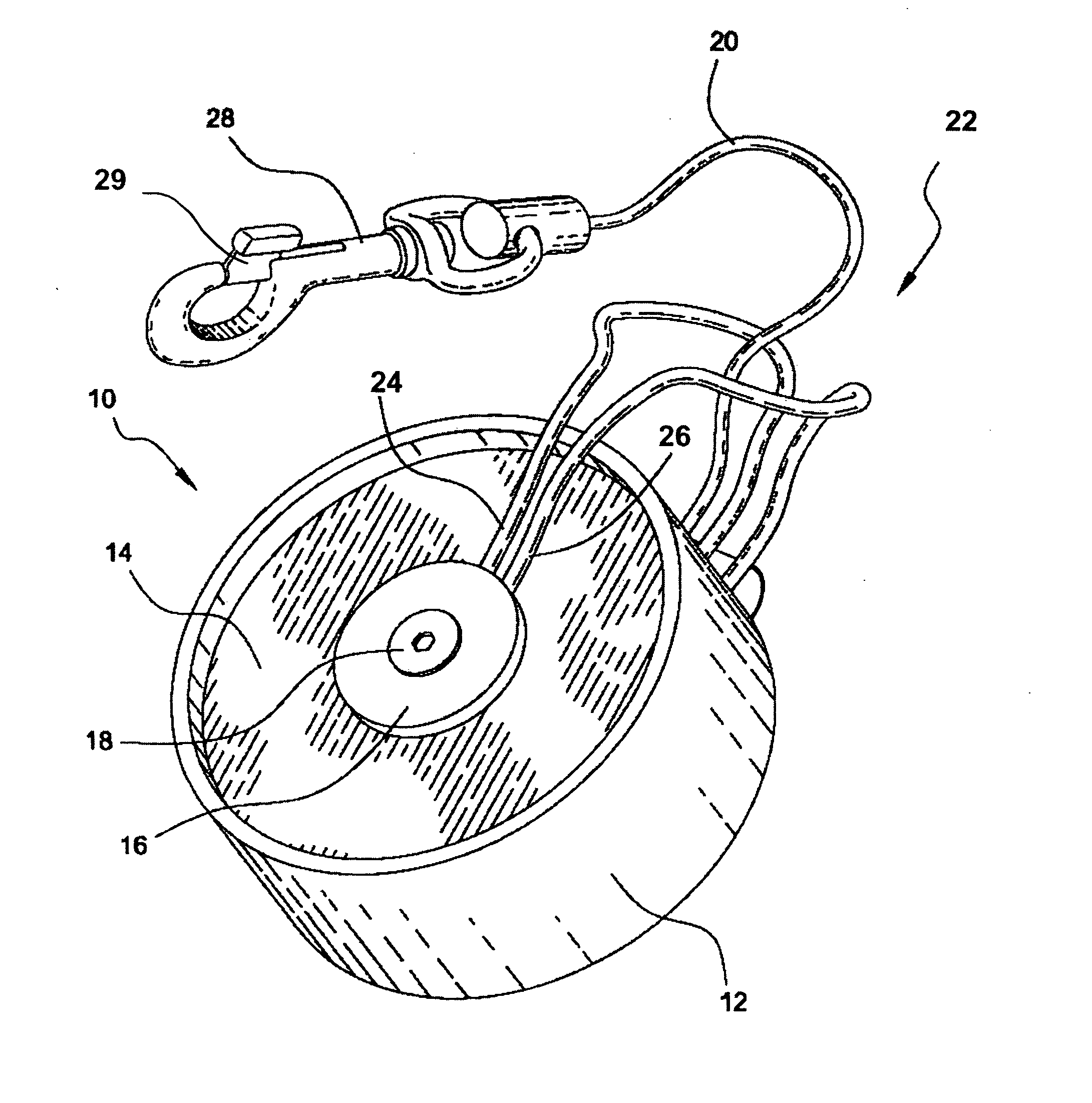
[0044] The present invention is illustrated in four different preferred embodiments. The first preferred embodiment is illustrated in FIGS. 1-5. The second preferred embodiment is illustrated in FIGS. 6-10. The third preferred embodiment is illustrated in FIGS. 11-15, and the fourth preferred embodiment is illustrated in FIGS. 16-20. Each preferred embodiment includes a common housing structure and each is differentiated by a unique cord control structure, as will be explained in greater detail hereinafter. The Figures use common reference numerals for structural elements common to all embodiments, and each embodiment along with the unique structural elements associated therewith have different reference numerals, even though such structural elements may perform like functions. The first preferred embodiment will be explained below, followed by descriptions of how the remaining embodiments differ structurally.

[0045] Even though there are structural differences between the preferred...


PUM


Abstract

A retractable tether device for tools for attachment to hand tools, including power tools includes a retractable tether or cord attached to a reel for extension and retraction thereof the distal end of the cord includes an attachment device for connecting the cord to a hand tool or other implement. A cord retaining arrangement is attached to the housing on the exterior thereof to selectively retain the cord against tension from the reel and from the power tool.

Description

BACKGROUND OF THE INVENTION [0001] The present invention relates broadly to retractable tether-based restraining devices and, more particularly, to a reel and retractable tether assembly for attachment to hand tools, including power tools with the reel housing including a restraining apparatus for the tether. [0002] Workers and others use hand tools that often need to be temporarily set aside in favor of other tools or other tasks for the workers hands. It will therefore be desirable to have some form of restraint on the tool that would allow a user to release a tool yet have the tool remain within reach for further use. The present invention is described in use with a power tool, specifically a power drill. This is done for clarity, and it will be understood by those skilled in the art that the present invention has application with all forms of hand tools, including a variety of power tools. [0003] In the recent past, a shoulder holster device similar to holsters used with firearm...

Claims


Application Information

Patent Timeline
IPC IPC(8): A45F5/00B65H75/40H01R13/72
CPCA45F5/021A45F5/004
Inventor WEAVER, WILLIAM WESLEY
Owner WEAVER WILLIAM WESLEY
Learn More