Charged droplet spray probe

a technology of spray probe and charged droplet, which is applied in the field of ion sources, can solve the problems of reducing ion production efficiency, poor spray stability, and disruption of the liquid surface and the associated production of charged liquid droplets, and achieves easy and inexpensive re-configuration, accurate and precise coaxial alignment, and high tolerance

Active Publication Date: 2005-11-24
PERKINELMER U S LLC
View PDF3 Cites 24 Cited by
  • Summary
  • Abstract
  • Description
  • Claims
  • Application Information

AI Technical Summary

Benefits of technology

[0014] It is another object of the present invention to provide an electrospray probe that is easily and inexpensively re-configured with fabricated from materials optimized for particular application requirements.
[0015] The foregoing and other objects of the invention are achieved with a nebulization-assisted electrospray probe with means to adjust the axial position of the central sample delivery tube relative to that of the outer nebulizing gas tube during operation, while simultaneously ensuring that accurate and precise coaxial alignment between the two tubes is always maintained independent of any axial adjustment. By capturing the tubes at multiple points within the disclosed probe and piloting the main sections to one another with high tolerance, improved mechanical stability and concentricity results. A linear translation mechanism provides for adjustment of the relative axial position of the tubes' ends without incorporating any rotation of either tube, thereby eliminating any mechanical distortions or misalignments associated with such rotations. The improved stability additionally allows more practical operation at lower flow rates than was previously possible with a pneumatic nebulization assisted probe, thereby extending the range of operation.
[0016] Further, both the inner and outer tubes may be fabricate

Problems solved by technology

The electric field causes charged species within the liquid to concentrate at the liquid surface at the end of the capillary, resulting in disruption of the liquid surface and the associated production of charged liquid droplets.
Typically, operation at liquid flow rates exceeding about 10-20 microliters/minute, depending on the solvent composition, leads to poor spray stability and droplets that are too large and polydisperse in size, resulting in reduced ion production efficiency.
Poor spray stability also results from solutions with high electrical conductivities and/or with a relatively high water content.
Because electrospray ion sources are often connected to liquid chromatographs for performing LC/MS, such limitations often conflict with requirements for achieving optimum chromatography, or may even preclude the use of LC/MS for many important classes of applications.
While such mechanical adjustments have proven essential for source optimization, nevertheless, the process of achieving maximum performance via such adjustments has frequently been found to be quite tedious.
Furthermore, once an optimum configuration

Method used


Image

  • Charged droplet spray probe
  • Charged droplet spray probe
  • Charged droplet spray probe

Examples


Embodiment Construction

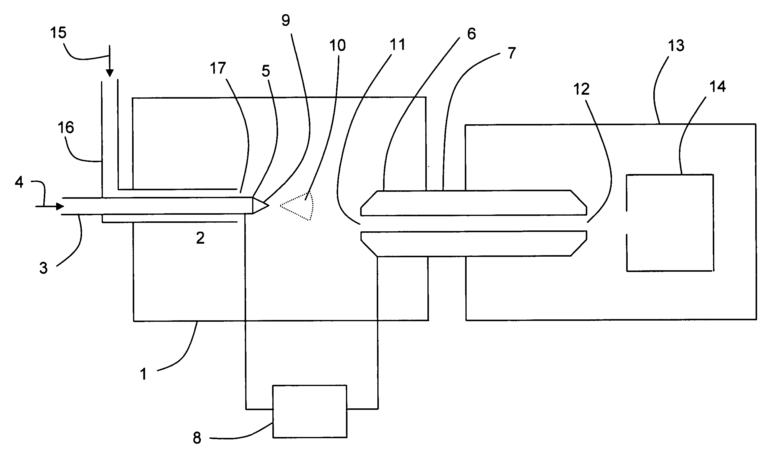
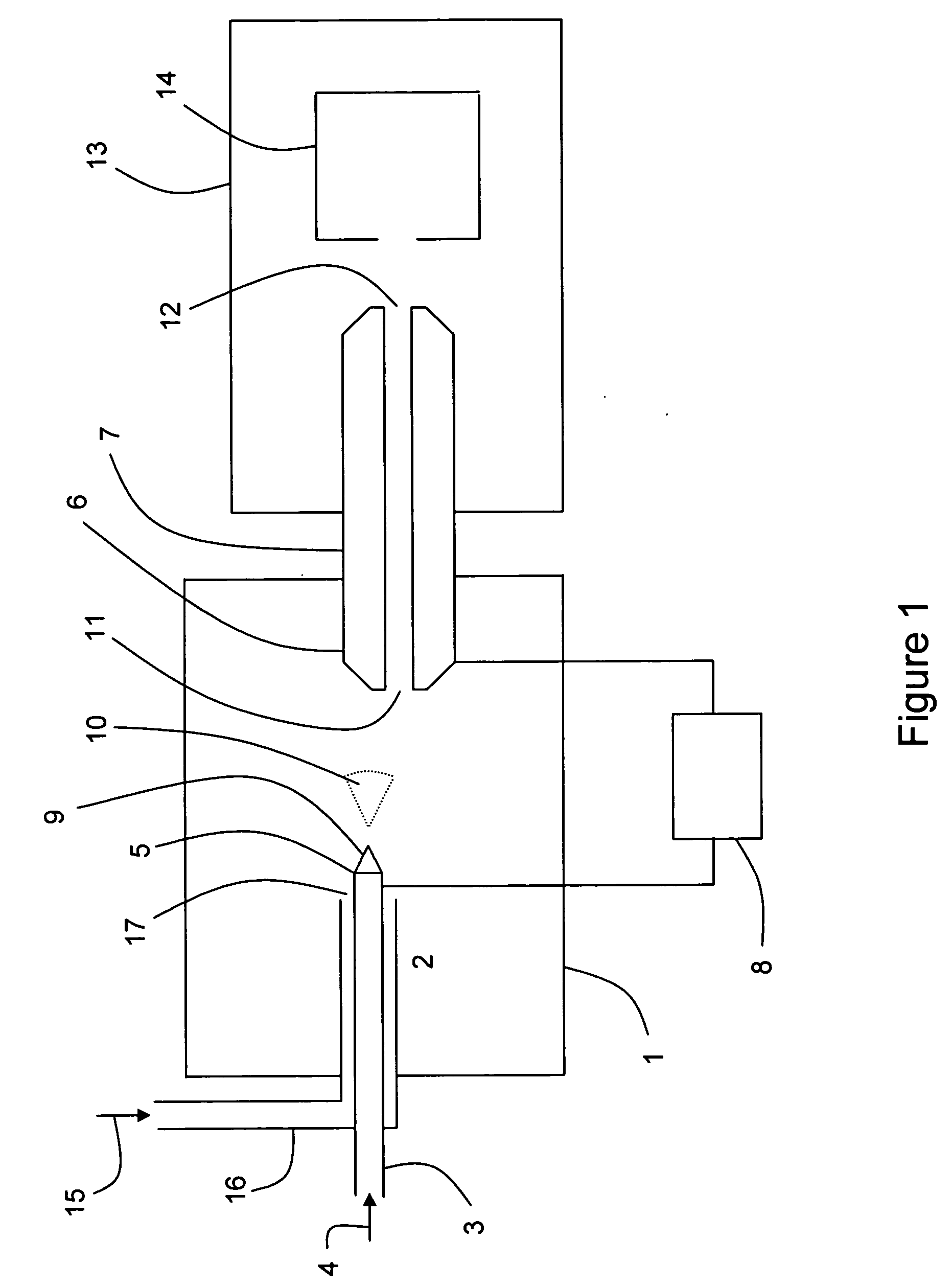
[0023] Turning now to a detailed description of preferred embodiments, FIG. 1 shows schematically a typical well-known configuration for a pneumatic nebulization-assisted electrospray ion source 1 in which the present invention would be incorporated. The source 1 includes a pneumatic nebulization assisted electrospray probe 2 essentially comprising liquid sample delivery tube 3 which delivers liquid sample 4 to sample delivery tube end 5. A voltage differential between tube end 5 and the entrance end 6 of capillary vacuum interface 7 is provided by high voltage DC power supply 8. The resulting electrostatic field in the vicinity of sample delivery tube end 5 results in the formation of an electrospray plume 10 from emerging sample liquid 9. Sample ions released from evaporating droplets within plume 10 are entrained in background gas flowing into capillary vacuum orifice 11, from which the ions are carried along with the gas to the capillary exit end 12 and into vacuum system 13. On...


PUM

PropertyMeasurementUnit
Dielectric polarization enthalpyaaaaaaaaaa
Electrical conductivityaaaaaaaaaa
Electric fieldaaaaaaaaaa

Abstract

An improved sample introduction probe is disclosed for the production of ions from liquid sample solutions in an electrospray ion source. Nebulization of a liquid sample emerging from the end of an inner flow tube is pneumatically assisted by gas flowing from the end of an outer gas flow tube essentially coaxial with the inner sample flow tube. The disclosed probe provides for adjustment of the relative axial positions of the ends of the liquid and gas flow tubes without degrading the precise concentricity between the inner and outer tubes. Additionally, the terminal portion of the outer gas flow tube may be fabricated either from a conductive or dielectric material, thereby allowing the pneumatic nebulization and electrospray processes to be optimized separately and independently. Hence, the disclosed invention provides a pneumatically-assisted electrospray probe with improved mechanical and operational stability, reliability, reproducibility, and ease of use compared to prior art probes.

Description

CROSS-REFERENCE TO RELATED APPLICATION [0001] This application claims priority to U.S. Provisional Application No. 60 / 573,665, filed on May 21, 2004, the disclosure of which is incorporated herein by reference in its entirety.FIELD OF THE INVENTION [0002] This invention relates generally to the field of ion sources, and, more specifically, to the field of electrospray ion sources which produce gas-phase ions from liquid sample solutions at or near atmospheric pressure for subsequent transfer into vacuum for mass-to-charge analysis. BACKGROUND OF THE INVENTION [0003] Electrospray ion sources have become indispensible in recent years for the chemical analysis of liquid samples by mass spectrometeric methods, owing in large part to their ability to gently create gas phase ions from sample solution species at or near atmospheric pressure. Electrospary ionization begins with the production of a fine spray of charged droplets when a liquid flows from the end of a capillary tube in the pre...

Claims


Application Information

Patent Timeline
IPC IPC(8): H01J49/00H01J49/04H01J49/16
CPCH01J49/167
Inventor WHITEHOUSE, CRAIG M.BURT, ALLANWHITEHOUSE, GLENNSANSONE, MIKE
Owner PERKINELMER U S LLC
Why Eureka
Try Eureka