Precompensated driver with constant impedance

a technology of impedance and driver, applied in the field of semiconductor products, can solve the problems of high output impedance, limited effect of practical digital filter, and increasing difficulty in using current sources in the output stag

Inactive Publication Date: 2005-11-24
IBM CORP
View PDF11 Cites 31 Cited by
  • Summary
  • Abstract
  • Description
  • Claims
  • Application Information

AI Technical Summary

Benefits of technology

[0015] Step #4. Determine the resistance across the terminals to wh

Problems solved by technology

The embodiment of a practical digital filter is typically limited by the designer for economic reasons in the number of voltage levels that can be driven and the duration that each

Method used


Image

  • Precompensated driver with constant impedance
  • Precompensated driver with constant impedance
  • Precompensated driver with constant impedance

Examples


Embodiment Construction

[0028] The invention will be described in detail with reference to the figures. It will be appreciated that this description and these figures are for illustrative purposes only, and are not intended to limit the scope of the invention. In particular, various descriptions and illustrations of the applicability, use, and advantages of the invention are exemplary only, and do not define the scope of the invention. Accordingly, all questions of scope must be resolved only from claims set forth elsewhere in this disclosure.

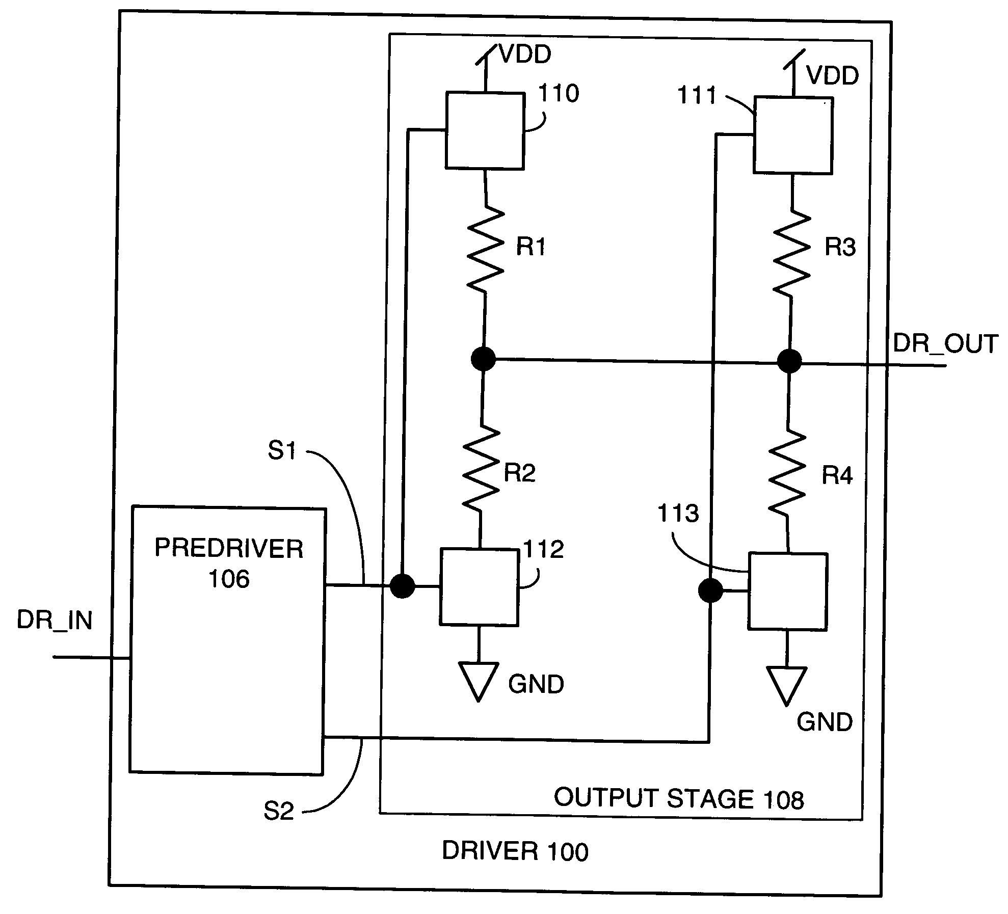
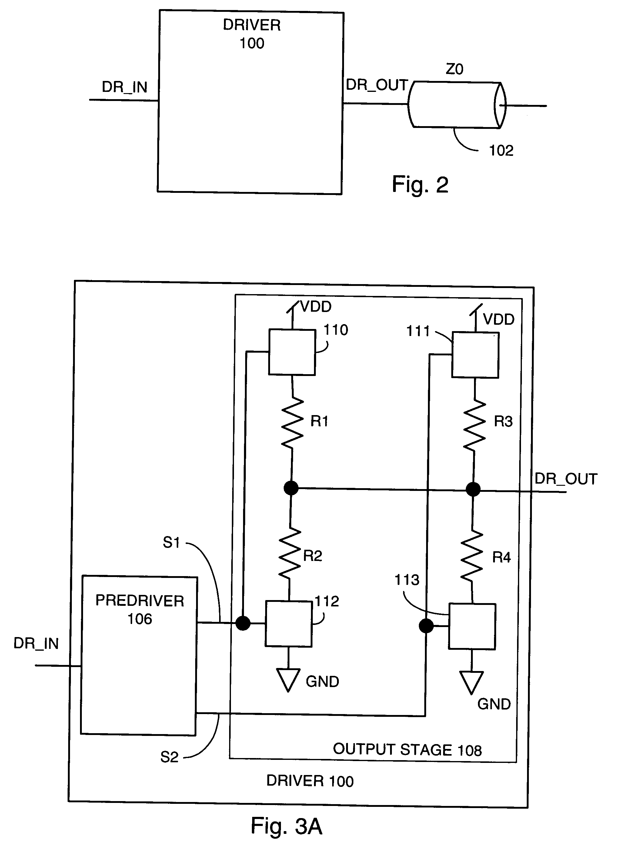
[0029] The current invention teaches methods and apparatus to transmit signals over a signal conductor using a precompensated driver that does not use a current source in the output stage, and which drives the signal conductor with an impedance similar to the characteristic impedance of the signal conductor.

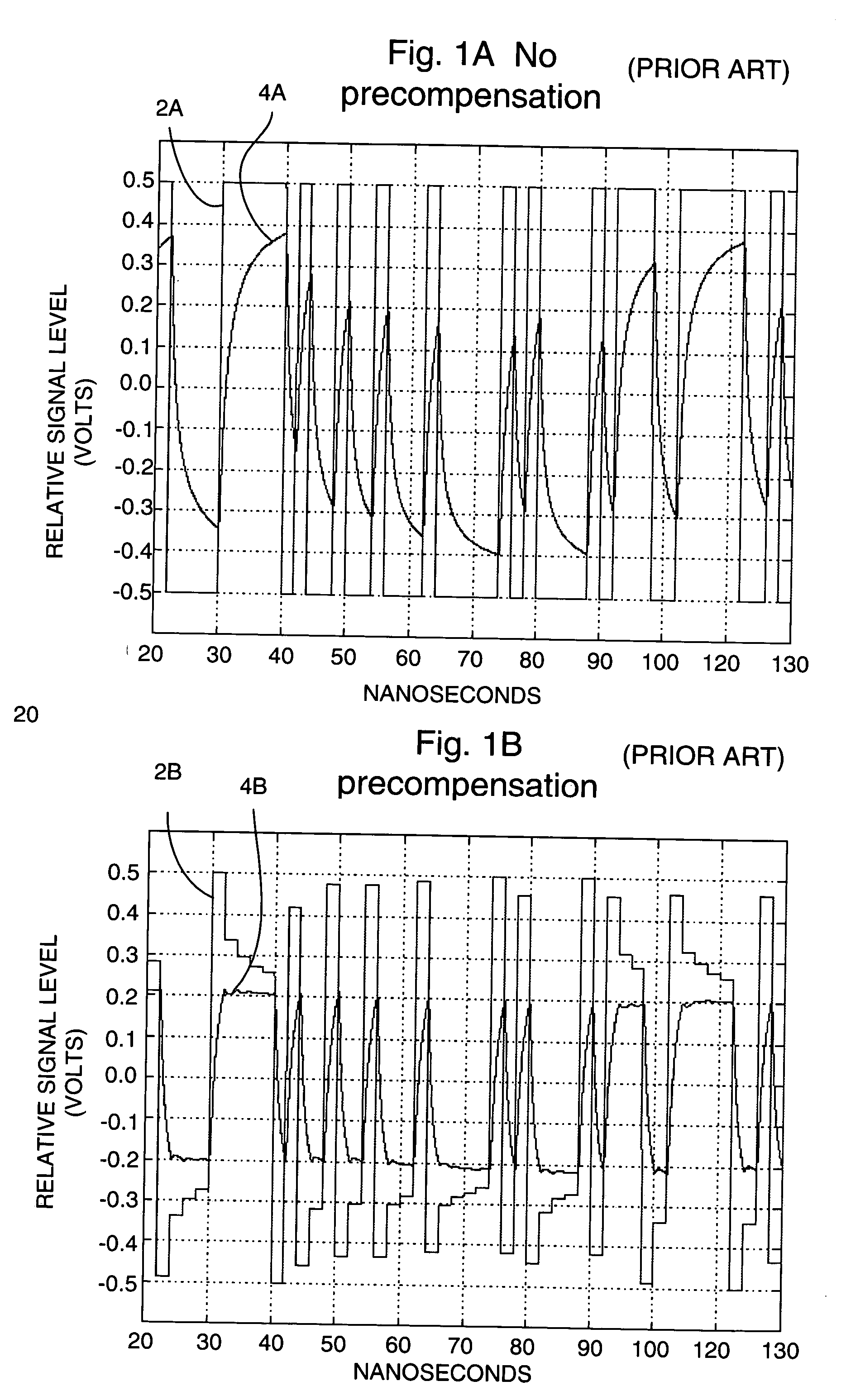
[0030]FIGS. 1A and 1B were described earlier to review the need for precompensation, and how precompensation can implement a transfer function that corrects for ...


PUM


Abstract

An apparatus and method is disclosed for transmitting signals over a signal conductor using a precompensated driver that does not use a current source, and which drives the signal conductor with an impedance similar to the characteristic impedance of the signal conductor. Since no current source is used, the precompensated driver can operate at very low supply voltage.

Description

BACKGROUND OF THE INVENTION [0001] 1. Field of the Invention [0002] The current invention generally relates to semiconductor products. More specifically, the current invention relates to high speed precompensated drivers [0003] 2. Description of the Related Art [0004] Components in electronic systems are generally interconnected by signal conductors, also known as transmission lines, which carry information sent from a first semiconductor chip to a second semiconductor chip. Such signal conductors are generally characterized by their inductance per unit length, capacitance per unit length, and attenuation per unit length. Skin effect attenuation on such signal conductors will distort a transmitted signal. This attenuation is frequency dependent and affects both the amplitude and phase of the transmitted signal. The skin effect attenuation reshapes data pulses in the transmitted signal and smears the signal in time so that adjacent bits overlap and interfere at a receiving end of the...

Claims


Application Information

Patent Timeline
IPC IPC(8): H03K19/094H04L25/02
CPCH04L25/0288H04L25/0278
Inventor MITBY, JOHN STEVENSILJENBERG, DAVID W.
Owner IBM CORP
Why Eureka
Try Eureka