Radial constrained lens

a radial constrained lens and aperture technology, applied in the direction of antennas, antenna details, antenna adaptation in movable bodies, etc., can solve the problems of multipath fading and multichannel interference becoming even more crucial issues, and the processing complexity is exponentially increasing

Active Publication Date: 2005-11-24
LEIDOS
View PDF3 Cites 20 Cited by
  • Summary
  • Abstract
  • Description
  • Claims
  • Application Information

AI Technical Summary

Problems solved by technology

As an example, the wireless local area network (WLAN) market is migrating to higher frequency spectra, higher data rates, and higher user densities so that multipath fading and multichannel interference are becoming even more crucial issues.

Method used


Image

  • Radial constrained lens
  • Radial constrained lens
  • Radial constrained lens

Examples


Embodiment Construction

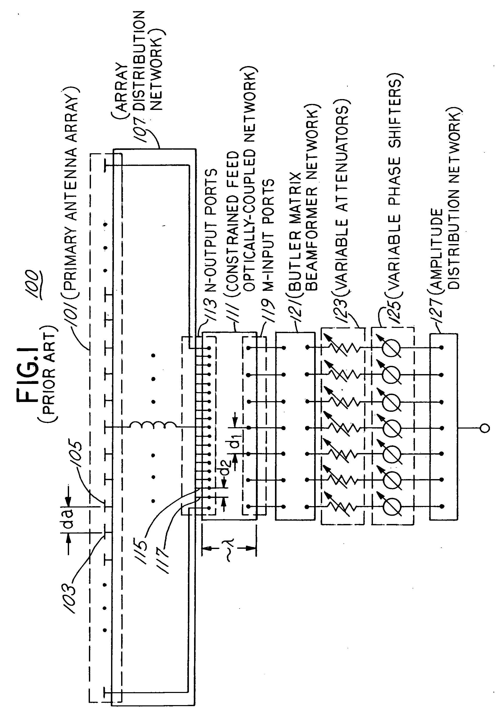
[0024]FIG. 1 shows scannable antenna system 100 in accordance with prior art as disclosed in U.S. Pat. No. 4,507,662 (“Optically Coupled, Array Antenna”, Rothenberg et al.). Scannable antenna system 100 includes a radiating array of antenna elements 101 that radiates (or receives) electromagnetic energy to an intended direction. Radiating array 101 contains N discrete antenna elements (e.g. antenna elements 103 and 105), where each antenna element is coupled, through equal line lengths, to first feed array 113, which is more closely spaced than radiating array 101. First feed array 113 comprises N feed elements (e.g., feed elements 115 and 117). Second feed array 119 is positioned to first feed array in close proximity, typically no more than a wavelength, through optically-coupled network 111. Second feed array 119 comprises M feed elements and has an inter-element spacing that is typically the same as the spacing between adjacent antenna elements. (M is an integer that is less tha...


PUM


Abstract

The invention provides apparatuses for a radial constrained lens in a steerable directional antenna system. The radial constrained lens includes a feed array that excites a continuous radiating aperture through a section of radial waveguide. Feed elements of the feed array are coupled to a feed network that processes a signal for each of the active feed elements. A feed array may include a plurality of feed probes or a plurality of waveguide sections. A sector, which includes a contiguous subset of feed elements, may be configured by a switching arrangement either in a transmit mode or a receive mode. The radial constrained lens may be commutated about a full 360 degree aperture view. Also, a plurality of radial constrained lens may be vertically stacked so that a scanned beam may be adjusted both in an azimuth and elevation directions.

Description

FIELD OF THE INVENTION [0001] The present invention relates to an antenna system having a cylindrical or conical aperture. In particular, the invention includes a feed mechanism that reduces the number of required feed elements. BACKGROUND OF THE INVENTION [0002] Steerable directional antennas are utilized in numerous applications for communications with the number of applications increasing with new services and needs. For example, steerable directional antennas play a major role in military applications that include synthetic aperture radar systems and phased array communication systems. Also, steerable directional antennas are being increasingly deployed in the commercial arena. As an example, the wireless local area network (WLAN) market is migrating to higher frequency spectra, higher data rates, and higher user densities so that multipath fading and multichannel interference are becoming even more crucial issues. Consequently, the wireless industry is investigating phased arra...

Claims


Application Information

Patent Timeline
IPC IPC(8): H01Q1/24H01Q3/24H01Q3/28H01Q3/36H01Q19/06H01Q21/20
CPCH01Q1/246H01Q3/24H01Q21/205H01Q3/36H01Q3/28
Inventor MILES, THOMAS
Owner LEIDOS
Why Eureka
Try Eureka