Reconfigurable radial-line slot antenna array

a radial-line slot, antenna array technology, applied in the direction of individual energised antenna arrays, polarised antenna unit combinations, linear waveguide fed arrays, etc., can solve the problems of inefficient space utilization or rely on costly components or assemblies

Active Publication Date: 2019-10-22
HUAWEI TECH CO LTD
View PDF13 Cites 6 Cited by
  • Summary
  • Abstract
  • Description
  • Claims
  • Application Information

AI Technical Summary

Problems solved by technology

Existing radial waveguide antenna structures that enable beam steering often rely on configurations that are not space efficient or rely on costly components or assemblies.

Method used


Image

  • Reconfigurable radial-line slot antenna array
  • Reconfigurable radial-line slot antenna array
  • Reconfigurable radial-line slot antenna array

Examples


Embodiment Construction

[0021]Disclosed herein are example embodiments for an agile antenna that beamsteers broadband wireless transmissions, e.g., signals in the RF or microwave frequency range. As used herein, the term RF frequencies and RF signals is used to represent frequencies and signals, respectively, in the RF, microwave, and other suitable regions of the spectrum for wireless communications.

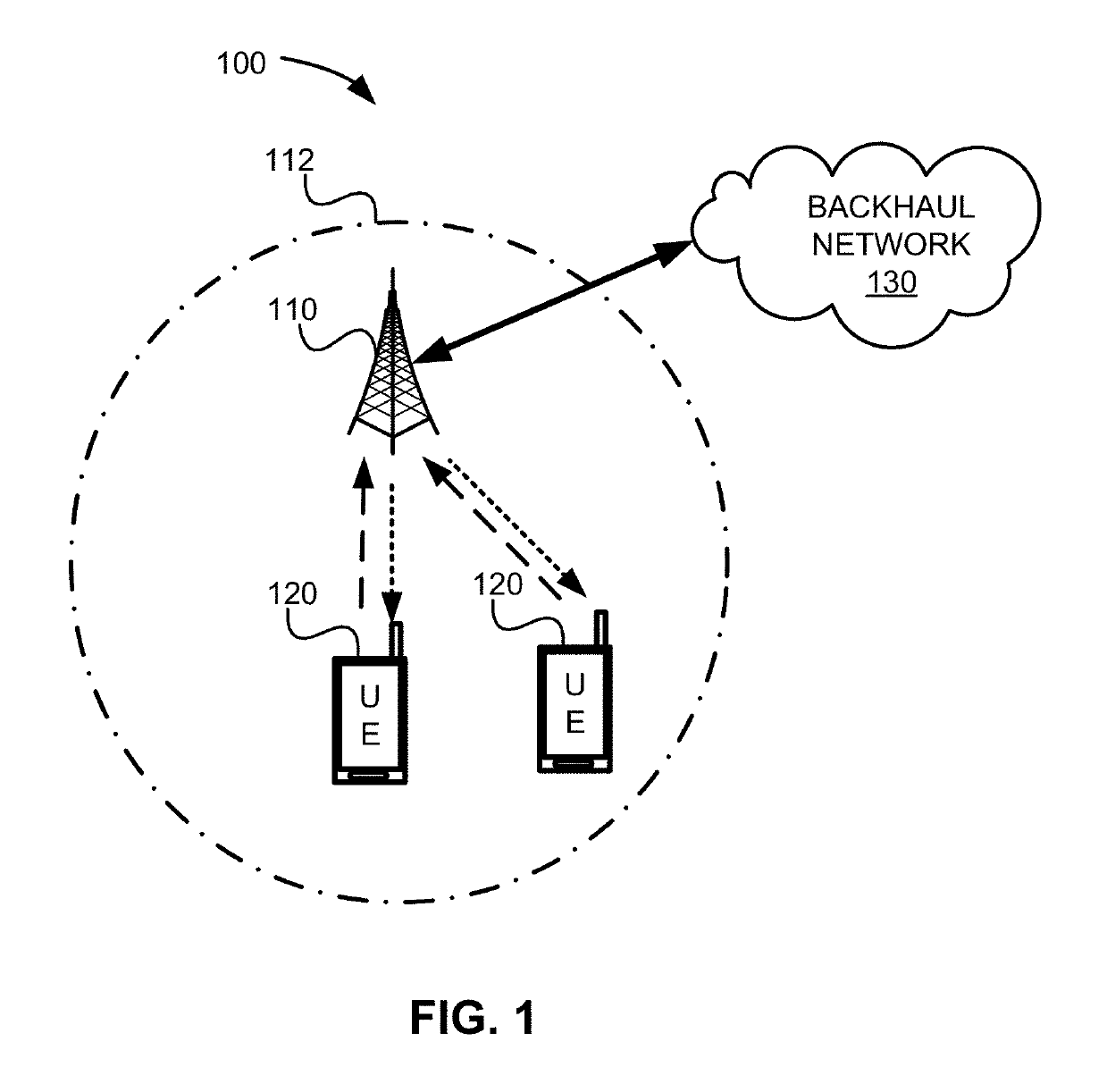
[0022]FIG. 1 illustrates a network 100 for communicating data. The network 100 comprises an access point (AP) 110 having a coverage area 112, a plurality of user equipments (UEs) 120, and a backhaul network 130. The AP 110 may comprise any component capable of providing wireless access, e.g., to establish uplink (dashed line) and / or downlink (dotted line) connections with the UEs 120. Examples of the AP 110 include a base station (nodeB), an enhanced base station (eNB), a femtocell, a Wireless LAN or WiFi access point, and other wirelessly enabled devices. The UEs 120 may comprise any components capable of est...


PUM


Abstract

An antenna that includes a radial waveguide defining a waveguide region between opposed first and second surfaces. A radio frequency (RF) probe is disposed in the waveguide region for generating RF signals, and a plurality of radiating slot antenna elements are disposed on the first surface for emitting the RF signals from the waveguide region. A plurality of spaced apart conductive elements are disposed within the waveguide region. The antenna includes tunable elements that each include a quarter wavelength RF choke coupled through a variable capacitance and an inductive line to a respective one of the conductive elements. A plurality of DC control lines are provided, with each DC control line being connected to at least one of the tunable elements to adjust the variable capacitance thereof. A control circuit is coupled to the DC control lines and configured to selectively apply DC current values to adjust the variable capacitances of the tunable elements to control a propagation direction of the RF signals from the RF probe.

Description

TECHNICAL FIELD[0001]The present disclosure relates to antenna design, and, in particular embodiments, to an apparatus and method for a reconfigurable radial-line slot antenna array.BACKGROUND[0002]Modern wireless transmitters of radio frequency (RF) signals or antennas perform beamsteering to manipulate the direction of a main lobe of a radiation pattern and achieve enhanced spatial selectivity. Conventional beamsteering techniques rely on manipulating the phase of RF signals through a series of phase shifters and RF switches. The inclusion of phase shifters, RF switches, and other complex components increase the manufacturing cost and design complexity of agile antennas. Accordingly, less complex agile antenna designs with broadband capabilities are desired.SUMMARY OF THE INVENTION[0003]Existing radial waveguide antenna structures that enable beam steering often rely on configurations that are not space efficient or rely on costly components or assemblies. Example embodiments are ...

Claims


Application Information

Patent Timeline
Patent Type & Authority Patents(United States)
IPC IPC(8): H01Q21/00H01Q21/22H01Q21/24
CPCH01Q21/24H01Q21/22H01Q21/005H01Q21/0012H01Q21/0056H01Q3/24H01Q21/0031H01Q5/385
Inventor BOUTAYEB, HALIMKLEMES, MAREKHYJAZIE, FAYEZ
Owner HUAWEI TECH CO LTD
Why Eureka
Try Eureka