

Apparatus with rectangular waveguide to radial mode transition
a rectangular waveguide and antenna technology, applied in the field of wireless communication, can solve the problems of long fabrication and test time, high variability of antenna performance between units, and significant labor and manufacturing costs
- Summary
- Abstract
- Description
- Claims
- Application Information
AI Technical Summary
Benefits of technology
Problems solved by technology
Method used
Image

Examples
example 1
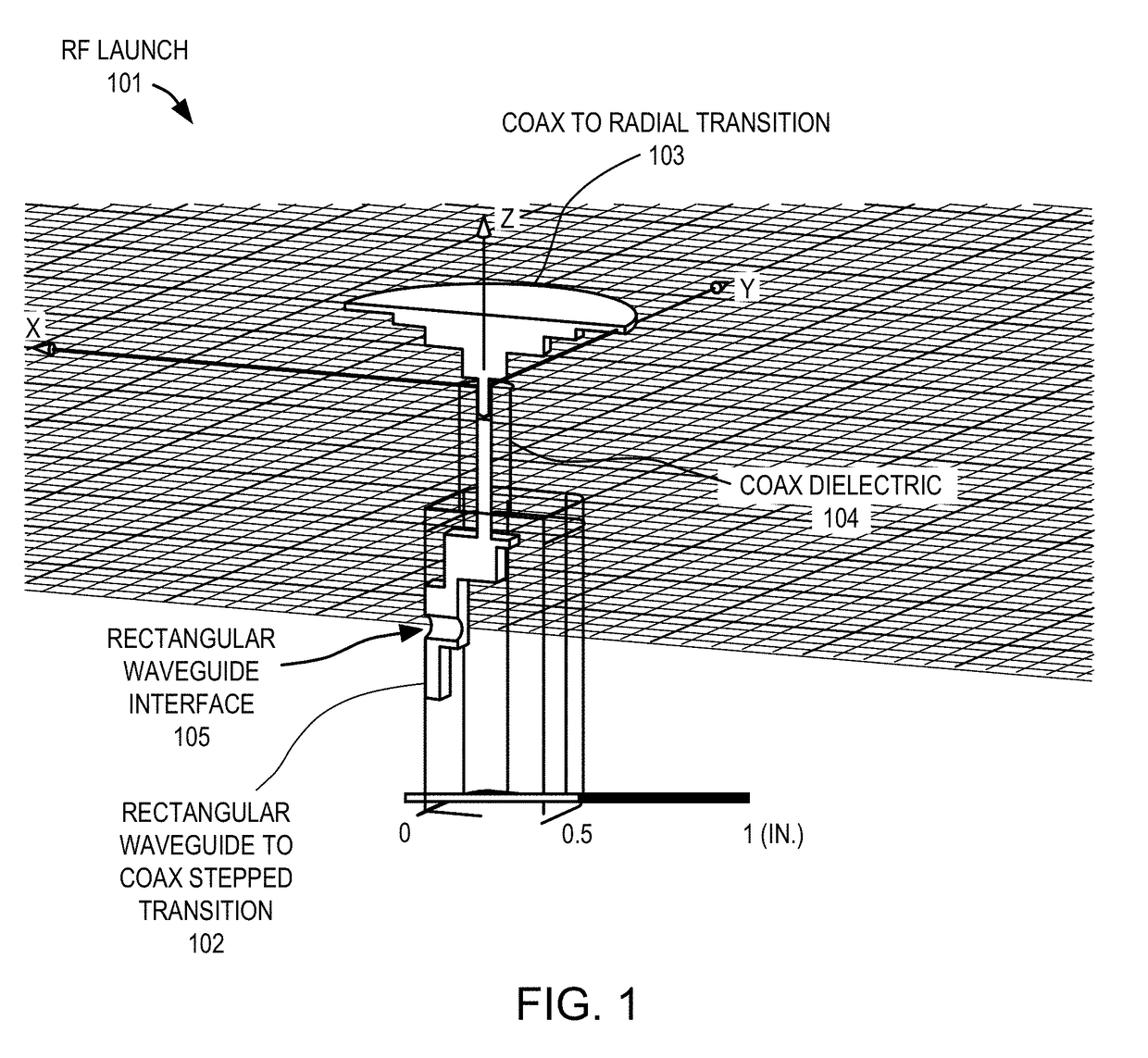
[0160 is an apparatus comprising: a radial waveguide having at least one plate; a radio-frequency (RF) launch coupled to the radial waveguide comprising a rectangular waveguide, a rectangular waveguide to coaxial transition coupled to the rectangular waveguide, and a coaxial to radial transition coupled to the rectangular waveguide to coaxial transition.
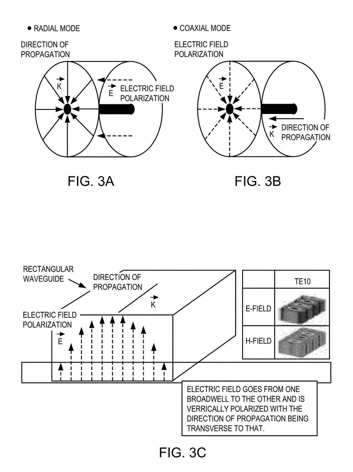
[0161]Example 2 is the apparatus of example 1 that may optionally include that the rectangular waveguide has a radial non-symmetric mode and the coaxial to radial transition has a radial symmetric mode.
[0162]Example 3 is the apparatus of example 1 that may optionally include that the rectangular waveguide to coaxial transition is coupled to the rectangular waveguide at a 90° angle.
[0163]Example 4 is the apparatus of example 1 that may optionally include that the coaxial to radial transition has a coaxial transmission line with a dielectric constant that is higher than air.
[0164]Example 5 is the apparatus of example 4 that may optiona...
example 11
[0170 is the apparatus of example 1 that may optionally include that the radial waveguide comprises a parallel plate waveguide.
[0171]Example 12 is the apparatus of example 1 that may optionally include that the RF launch is operable to input a feed wave that propagates concentrically from the RF launch.
[0172]Example 13 is an apparatus comprising: a radial waveguide having at least one plate; a radio-frequency (RF) launch coupled to the radial waveguide comprising a rectangular waveguide, a rectangular waveguide to stripline transition coupled to the rectangular waveguide, and a stripline to radial transition coupled to the rectangular waveguide to coaxial transition.
[0173]Example 14 is the apparatus of example 13 that may optionally include that the rectangular waveguide has a radial non-symmetric mode and the stripline to radial transition has a radial symmetric mode.
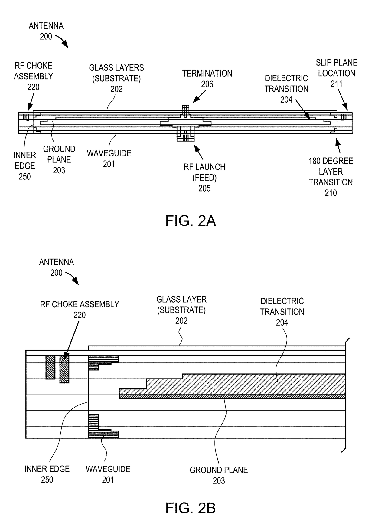
[0174]Example 15 is an antenna comprising: a radial parallel plate waveguide; a radio-frequency (RF) launch coupled ...
example 16
[0175 is the antenna of example 15 that may optionally include that the rectangular waveguide to coaxial stepped transition is coupled to the rectangular waveguide at a 90° angle.
[0176]Example 17 is the antenna of example 15 that may optionally include that the coaxial to radial transition has a coaxial transmission line insulator with a dielectric constant that is higher than air.
[0177]Example 18 is the antenna of example 17 that may optionally include that the coaxial transmission line is configured to maintain a pin of the coaxial to radial transition in a centered position with respect to the coaxial to radial transition.
[0178]Example 19 is the antenna of example 15 that may optionally include that the rectangular waveguide to coaxial stepped transition is coupled to the coaxial to radial transition via a pin.
[0179]Example 20 is the antenna of example 19 that may optionally include that the coaxial to radial transition has the pin and the pin is fit in a pin receptacle of the re...
PUM
 Abstract
Description
Claims
Application Information