
Antenna aperture with clamping mechanism

a technology of clamping mechanism and antenna, which is applied in the direction of loop antenna, radiating element structure, particular array feeding system, etc., can solve the problems of limited average power handling capacity of the launch, inability to extend beyond 20% bandwidth, and inherently limited resonance of the launch structur

Active Publication Date: 2018-11-08
KYMETA
View PDF2 Cites 7 Cited by
  • Summary
  • Abstract
  • Description
  • Claims
  • Application Information

AI Technical Summary

Benefits of technology

The patent describes an antenna that has a way to hold the parts together. The antenna has a part that guides the signals and a part that emits the signals. The parts are clamped together to make sure they fit together well and work together well. This makes the antenna easier to use and more effective at transmitting signals.

Problems solved by technology

The resonance of the launch structure is inherently band limited and difficult to extend beyond 20% bandwidth without adding other tuning mechanisms to compensate for the resonance.
The free standing probe also limits the average power handling capacity of the launch to roughly 10 watts or less for a standard SubMiniature version A (SMA) center pin.
Any heat accumulated at the launch will be dissipated only through radiation or convection, which will be limited due to the surface area of the probe and the air flow within the waveguide cavity.
While this approach can achieve broad bandwidths, the fabrication can become difficult due to the complex curves that create these smooth transitions.
Development of LCD / glass-based radiating apertures based on dielectric substrates without external metallization layers prevents providing an electrical attachment method similar to the conventional methods described above.

Method used


Image

  • Antenna aperture with clamping mechanism
  • Antenna aperture with clamping mechanism
  • Antenna aperture with clamping mechanism

Examples


example embodiments

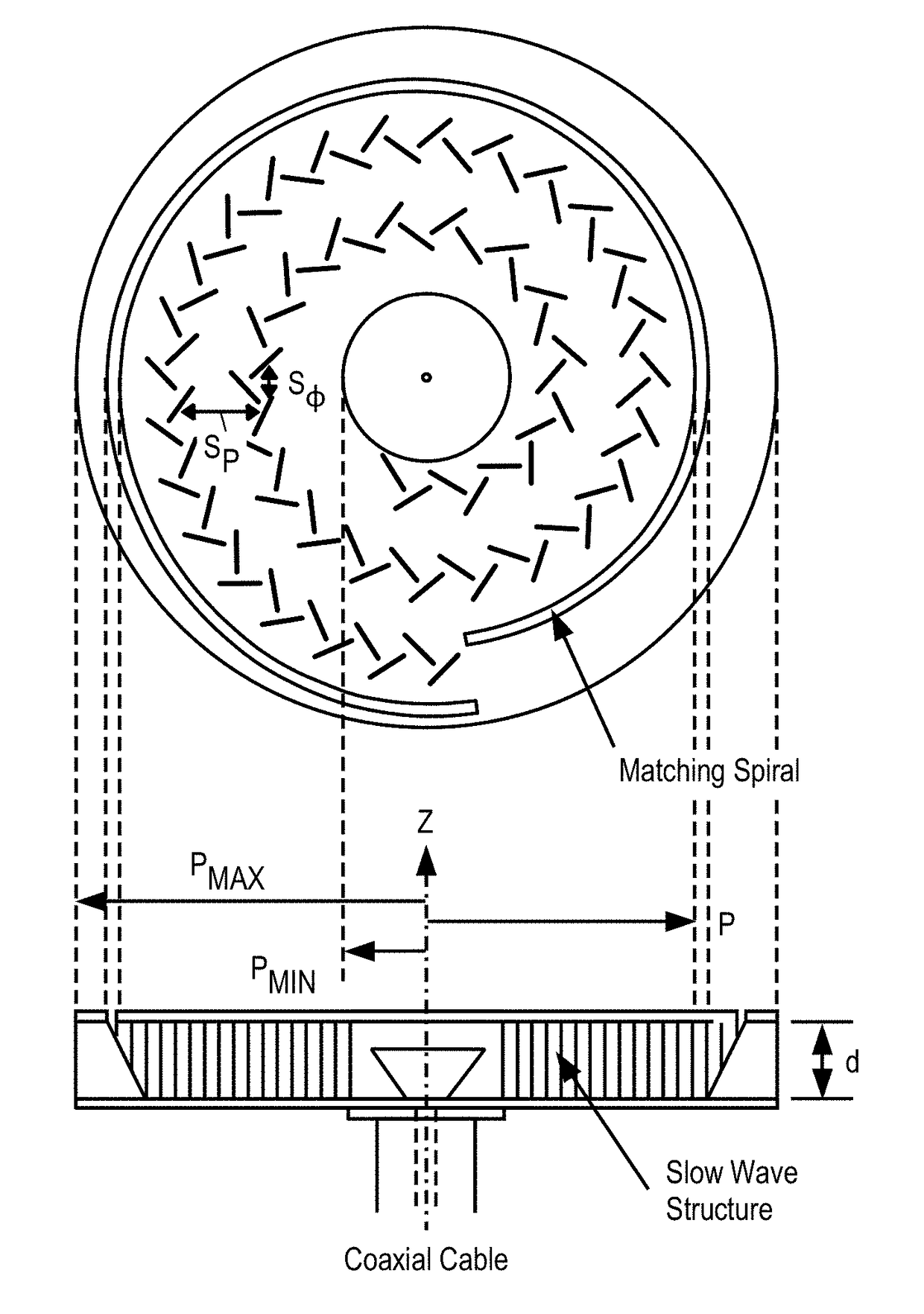
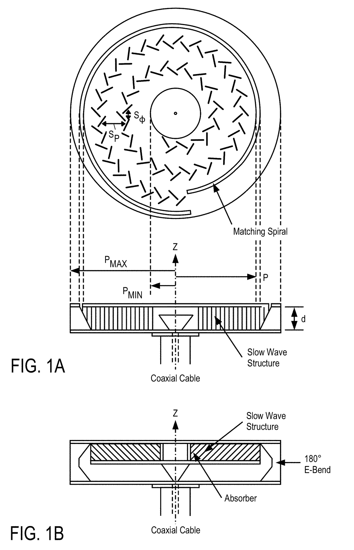
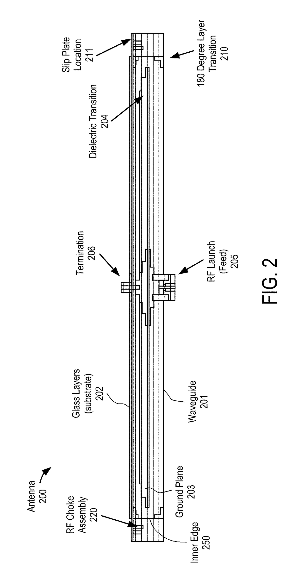
[0032]In one embodiment, the spring clamp design as incorporated into the antenna assembly provides for a consistent compressive mating force between the antenna aperture and the antenna feed (e.g., waveguide) for improved RF performance and to prevent excessive displacements of aperture and feed component stresses that may rise and stress that arises between such components during vibration and shock, allows for antenna aperture and feed vertical height tolerance accumulations, enables antenna aperture and feed attachment to each other without permanent bonding, and supports alignment between the antenna aperture and feed in X and Y axis (i.e., two axis's), while allowing for all of the above within the tight dimensional and volume constraints of the antenna assembly.

[0033]In one embodiment, series of spring clamps attach to the waveguide structure by threaded fasteners providing a vertical clamping function to compress the aperture assembly to the feed. The location and geometry o...

examples of antenna embodiments

[0070]The techniques described above may be used with flat panel antennas. Embodiments of such flat panel antennas are disclosed. The flat panel antennas include one or more arrays of antenna elements on an antenna aperture. In one embodiment, the antenna elements comprise liquid crystal cells. In one embodiment, the flat panel antenna is a cylindrically fed antenna that includes matrix drive circuitry to uniquely address and drive each of the antenna elements that are not placed in rows and columns. In one embodiment, the elements are placed in rings.

[0071]In one embodiment, the antenna aperture having the one or more arrays of antenna elements is comprised of multiple segments coupled together. When coupled together, the combination of the segments form closed concentric rings of antenna elements. In one embodiment, the concentric rings are concentric with respect to the antenna feed.

Examples of Antenna Systems

[0072]In one embodiment, the flat panel antenna is part of a metamateri...


PUM


Abstract

An antenna with a clamping mechanism and a method for using the same are disclosed. In one embodiment, an antenna comprises a radial waveguide, an aperture operable to radiate radio frequency (RF) signals in response to an RF feed wave fed by the radial waveguide, and one or more clamping devices to apply a compressive force between the waveguide and the aperture.

Description

PRIORITY[0001]The present patent application claims priority to and incorporates by reference the corresponding provisional patent application Ser. No. 62 / 501,566, titled, “Spring Clamp Design to Mate Aperture and Varying Feed in RF Antenna,” filed on May 4, 2017.FIELD OF THE INVENTION[0002]Embodiments of the present invention relate to the field of antennas; more particularly, embodiments of the present invention relate to antenna apertures with multiple layers secured in place with a clamping mechanism.BACKGROUND OF THE INVENTION[0003]Traditional planar antennas that integrate a radiating aperture and feed structure ensure a physical conductive connection between the two subassemblies to provide a current return path for direct current (DC) control and power conditioning signals as well as RF signals to prevent extraneous radiation from the electrical interface from corrupting the radiation patterns of the antenna. Typical feed structures in these types of antennas tend to feed RF...

Claims


Application Information

Patent Timeline
Patent Type & Authority Applications(United States)
IPC IPC(8): H01Q1/12H01Q21/00
CPCH01Q1/1207H01Q21/0012H01Q19/027H01Q1/38H01Q1/405H01Q3/26H01Q9/0442H01Q1/243H01Q1/242H01Q7/00
Inventor HARP, KENLAIRD, BRADMOREY, ROBERTTURNER, ANDREWCHEN, FELIX
Owner KYMETA
Learn More