Optical scanning apparatus and image forming apparatus using the same

a scanning apparatus and optical scanning technology, applied in the direction of electrographic process apparatus, instruments, printing, etc., can solve the problems of degrading image quality, affecting the output quality of multiplex images or full-color images, and affecting the output quality of images, so as to reduce suppress scanning line bending. , the effect of reducing the thickness of light deflectors

Inactive Publication Date: 2005-11-24
CANON KK
View PDF1 Cites 3 Cited by
  • Summary
  • Abstract
  • Description
  • Claims
  • Application Information

AI Technical Summary

Benefits of technology

[0023] An object of the present invention is to provide an optical scanning apparatus, which is provided with preferable optical performance by reducing the thickness of a light deflector and by suppressing scanning line bending on a surface to be scanned, and an image forming apparatus that uses the optical scanning apparatus.

Problems solved by technology

In particular, when a full-color image is to be obtained by performing multicolor development, even a slight misregistration leads to degradation of image quality.
In the case of 400 dpi, for instance, even misregistration of a fraction of one pixel (one pixel corresponds to 63.5 μm) results in a change appeared as color misregistration or color tint drift, and significantly degrades image quality.
With this method, however, there has been a problem in that it takes a long time to output a multiplex image or a full-color image.
In this case, however, there is apprehension that color misregistration will occur when the images are superimposed one another.
In this case, there has been a problem in that optical components are required as many as the imaging optical systems, which increases cost because the light deflector (polygon mirror) and the like in particular are expensive.
Also, in the case of particularly high-speed and high-definition imaging optical systems, the problem becomes more serious because the light deflectors are increased in size and required to have capacities for high-speed deflection at the same time.
With the conventional method, however, light beams other than a light beam having a small incident angle in the sub-scanning direction need to be made incident onto the polygon mirror at larger angles, which tends to increase the beam incident angles onto the polygon mirror in the sub-scanning section.
In a case where a light beam is obliquely made incident on a polygon mirror with a large angle in a sub-scanning section, there has been a problem in that a position of the deflecting surface of the polygon mirror moves back and forth, which causes so-called pitch unevenness in which a beam reaching position in the sub-scanning direction is displaced.
In this case, however, the cost is increased.
Also, when it is impossible to adopt a high-precision polygon mirror, image quality is degraded.
In addition, if the oblique incident angle is large, there have been such problems in that bending of a scanning line is easy to occur, and in that spot performance is deteriorated.

Method used


Image

  • Optical scanning apparatus and image forming apparatus using the same
  • Optical scanning apparatus and image forming apparatus using the same
  • Optical scanning apparatus and image forming apparatus using the same

Examples


first embodiment

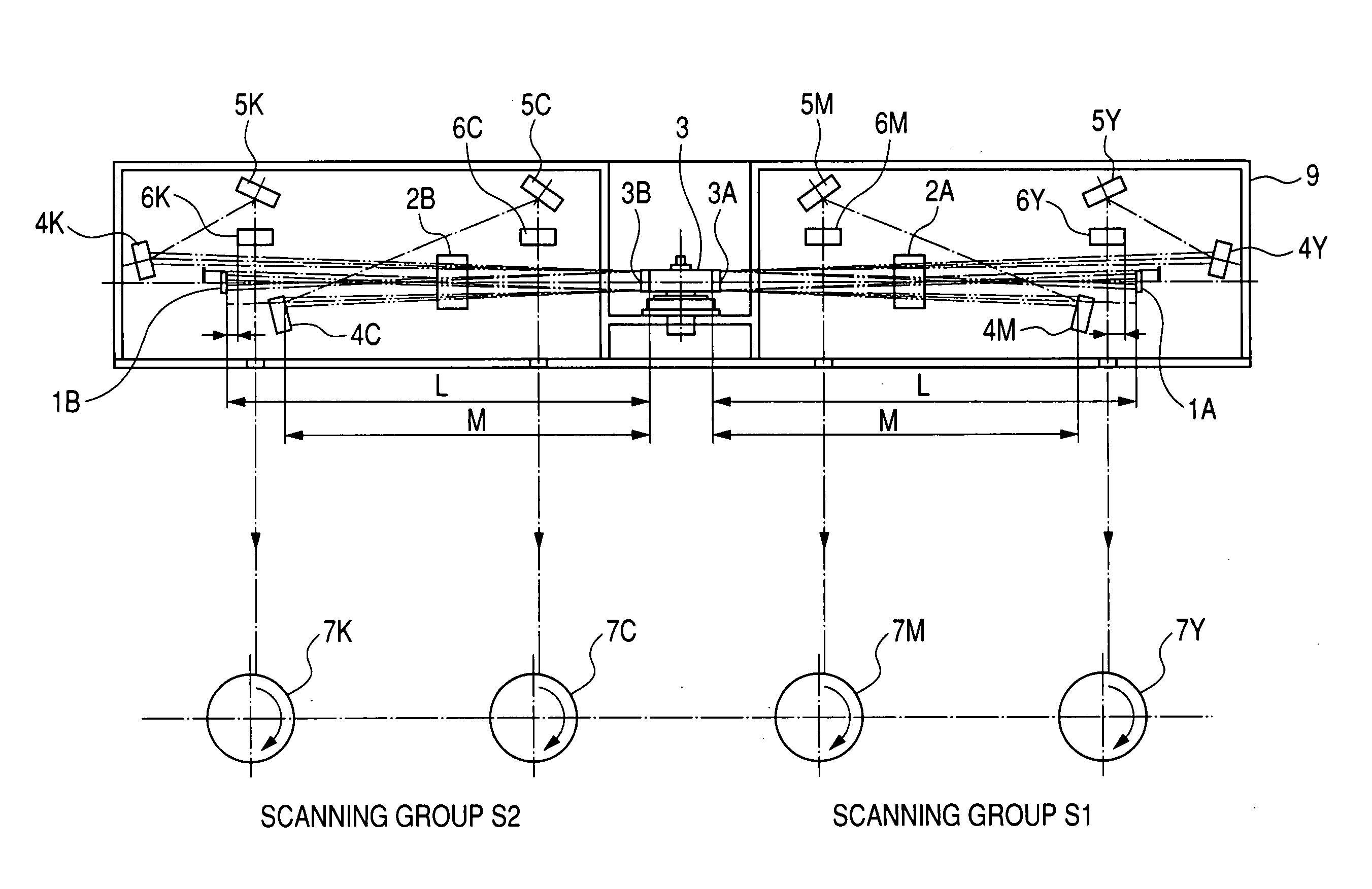
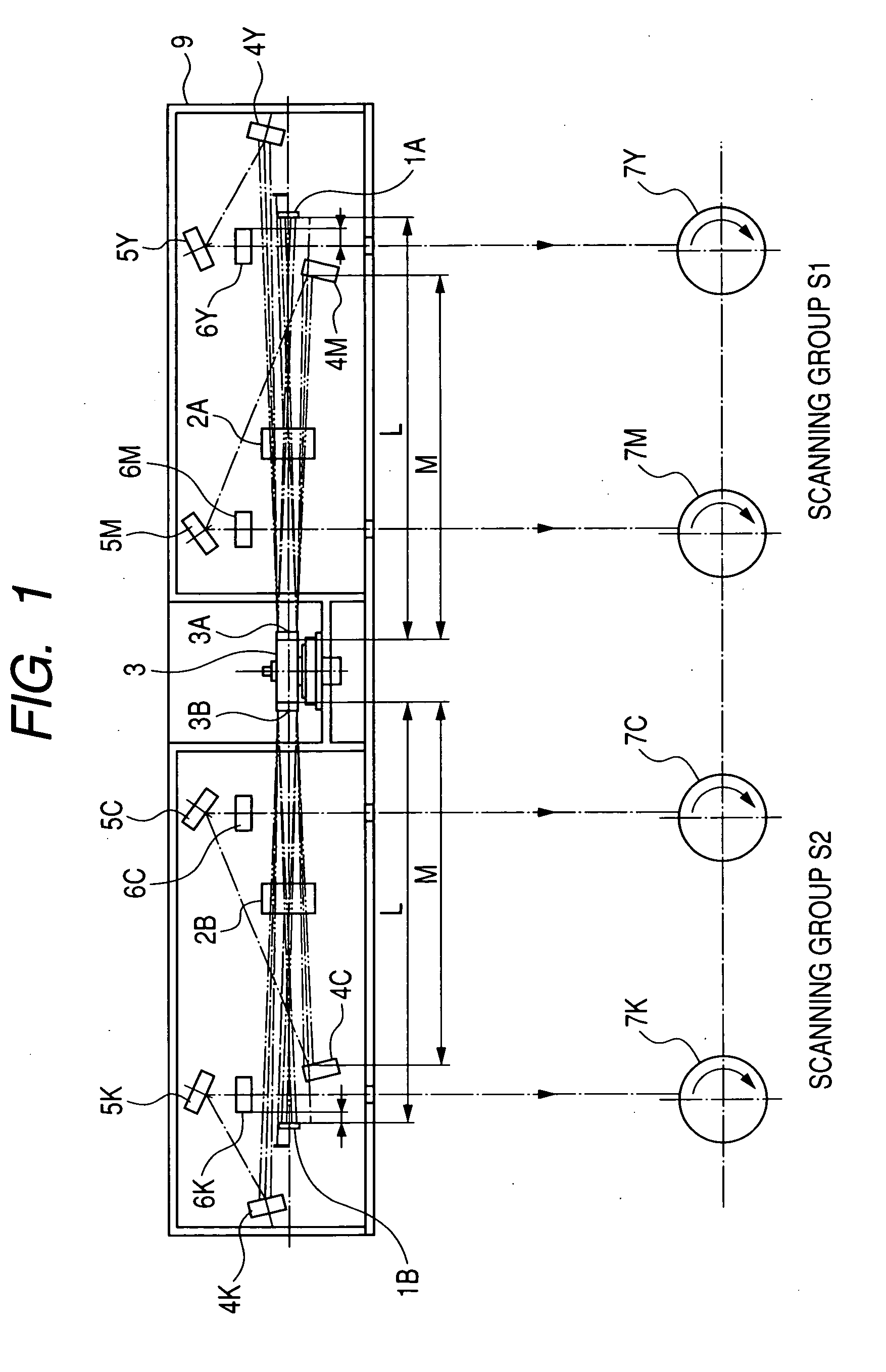
[0042]FIG. 1 is a main portion sectional view (sub-scanning sectional view) taken in a sub-scanning direction of a first embodiment of the present invention.

[0043] Here, a main scanning direction refers to a direction perpendicular to a rotation axis of a light deflector and to an optical axis of an imaging optical system (direction in which a light beam is reflected and deflected (deflected and scanned) by the light deflector), and the sub-scanning direction refers to a direction parallel to the rotation axis of the light deflector. Also, a main scanning section refers to a plane parallel to the main scanning direction and containing the optical axis of the imaging optical system, and a sub-scanning section refers to a section perpendicular to the main scanning section.

[0044] In this embodiment, multiple light beams from multiple light source means (not shown) that each emit multiple light beams (two light beams are emitted in this embodiment, although three or more light beams m...

second embodiment

[0094]FIG. 4 is a main portion sectional view (sub-scanning sectional view) taken in the sub-scanning direction and showing the vicinity of an incident system turn back mirror and the vicinity of a deflecting surface of a polygon mirror in a second embodiment of the present invention.

[0095] This embodiment differs from the first embodiment described above in that first turn back mirrors (43y and 43M) of a scanning system are disposed at positions farther from the light deflector than an incident system turn back mirror 41 from the light deflector. The rest of the construction and optical action are set approximately the same as those in the first embodiment, thereby providing the same effects.

[0096] That is, in the drawing, reference numeral 41 (corresponding to 1A in FIG. 1) denotes an incident system turn back mirror and reference numeral 42 (corresponding to 3A in FIG. 1) represents a deflecting surface of a polygon mirror. Reference numerals 43Y and 43M (corresponding to 4Y an...


PUM


Abstract

Provided are an optical scanning apparatus, which keeps an oblique incident angle to be small with respect to a polygon mirror in a sub-scanning section to provide preferable optical performance with a compact and simple construction, and an image forming apparatus using the optical scanning apparatus. The optical scanning apparatus includes a plurality of light source means, an incident system turn back mirror that reflects light beams emitted from the plurality of light source means, a light deflector that deflects the plurality of light beams using the same deflecting surface, and an imaging optical system that guides the light beams deflected by the light deflector respectively onto a plurality of surfaces to be scanned. At the time of light-scanning of the plurality of surfaces to be scanned, the incident system turn back mirror is disposed in an effective scanning range in a main scanning section when it is projected in the main scanning section. Also, in the sub-scanning section, the multiple light beams are reflected by the incident system turn back mirror in mutually different directions with respect to the normal line direction of the incident system turn back mirror, and then made incident at mutually different angles with respect to the same deflecting surface of the light deflector.

Description

BACKGROUND OF THE INVENTION [0001] 1. Field of the Invention [0002] The present invention relates to an optical scanning apparatus and an image forming apparatus using the optical scanning apparatus. In particular, the present invention relates to an optical scanning apparatus, which is suited for an image forming apparatus such as a laser beam printer (LBP), a digital copying machine, or a multifunctional printer (versatile printer) each including an electrophotographic process. In the optical scanning apparatus, a light beam emitted from light source means is reflected and deflected by a polygon mirror serving as a light deflector and passes through an imaging optical system, then a surface to be scanned is scanned with the light beam to record image information. [0003] 2. Related Background Art [0004] Conventionally, in an image forming apparatus such as a laser beam printer or a digital copying machine, a light flux (beam) light-modulated in accordance with an image signal and e...

Claims


Application Information

Patent Timeline
Patent Type & Authority Applications(United States)
IPC IPC(8): B41J2/44B41J2/47B41J15/14B41J27/00G02B17/08G02B26/08G02B26/10G02B26/12G03G15/01G03G15/04H04N1/036H04N1/113
CPCB41J2/473G02B26/125G02B26/123
Inventor TAKAYAMA, HIDEMI
Owner CANON KK
Why Eureka
Try Eureka