Optical scanning apparatus and image forming apparatus using the same

a scanning apparatus and image technology, applied in the field of optical scanning apparatus and image forming apparatus, can solve the problems of deteriorating image, affecting the quality of the image, and deteriorating the image, and achieve the effect of convenient optical performance and simple and compact structur

Active Publication Date: 2006-03-16
CANON KK
View PDF8 Cites 4 Cited by
  • Summary
  • Abstract
  • Description
  • Claims
  • Application Information

AI Technical Summary

Benefits of technology

[0020] An object of the present invention is to provide a simple and compact optical scanning apparatus in which an optical deflector is thinned, a scanning line curvature on a surface to be scanned is suppressed, and preferable optical performance is obtained, and an image forming apparatus using the optical scanning apparatus.

Problems solved by technology

In particular, even if a slight superimposition displacement occurs in a multi-color development, an obtained full color image deteriorates.
For example, even if a superimposition displacement of a fraction of one pixel, 63.5 μm, occurs in the case of 400 dpi, it appears as a color misregistration, thereby significantly deteriorating the image.
However, this method has contained a problem that it takes time to output a multi-image or a full color image.
In such a method, there may be a concern over a color misregistration when the images are superimposed.
In the image forming apparatus, since there needs optical parts as many as the scanning optical systems, and in particular, the optical deflector (polygon mirror) is expensive, there is a problem that a cost of the image forming apparatus may rise.
Therefore, the problem is serious.
As a result, there is a problem that the polygon mirror becomes larger in thickness to increase a cost of the image forming apparatus.
As a result, there is a problem that a cost reduction effect is small.

Method used


Image

  • Optical scanning apparatus and image forming apparatus using the same
  • Optical scanning apparatus and image forming apparatus using the same
  • Optical scanning apparatus and image forming apparatus using the same

Examples


embodiment 1

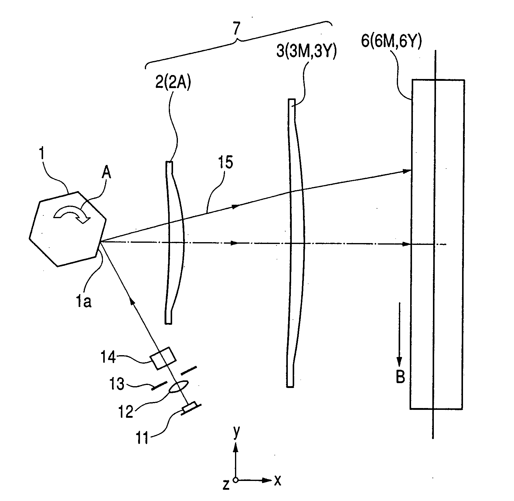
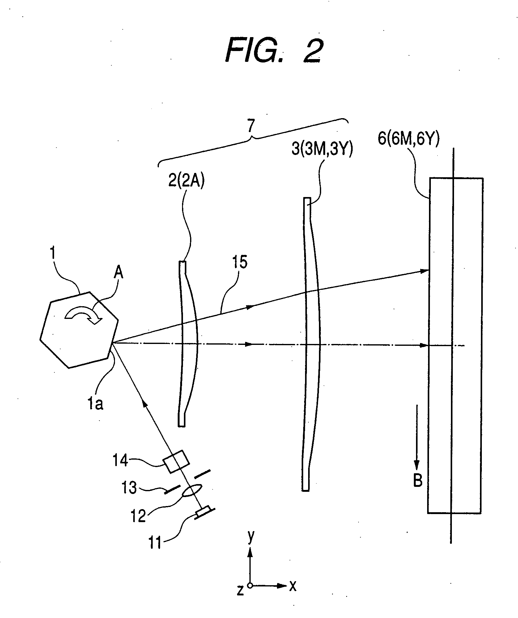
[0057]FIG. 1 is a main part sectional view (sub scanning sectional view) showing an optical scanning apparatus (image forming apparatus) in a sub scanning direction according to Embodiment 1 of the present invention.

[0058] Here, a main scanning direction indicates a direction perpendicular to the rotational axis of an optical deflector and the optical axis of a scanning optical system (direction in which a light beam is reflected and deflected (is deflected with scanning) by the optical deflector). The sub scanning direction indicates a direction parallel to the rotational axis of the optical deflector. A main scanning section indicates a plane which is parallel to the main scanning direction and includes the optical axis of the scanning optical system. A sub scanning section indicates a section perpendicular to the main scanning section.

[0059] In this embodiment, a plurality of light beams which are emitted from a light source and modulated according to an image signal are divide...

embodiment 2

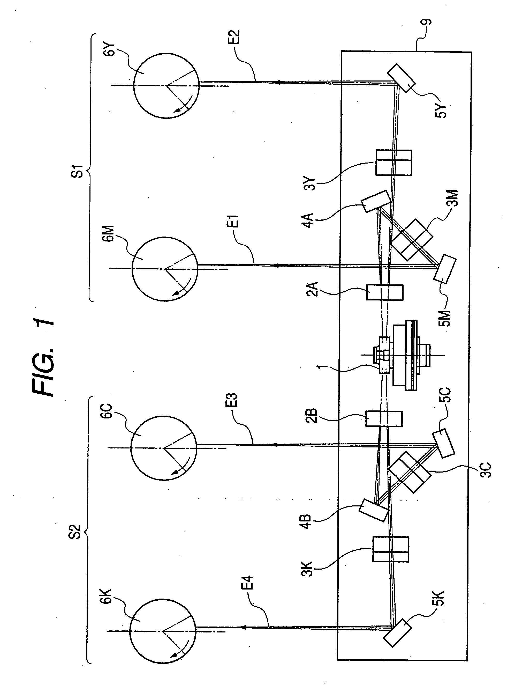
[0137]FIG. 14 is a schematic diagram showing a main part of a color image forming apparatus according to embodiment 2 of the present invention.

[0138] This embodiment corresponds to a tandem type color image forming apparatus in which the optical scanning apparatus according to embodiment 1 is used for scanning with four beams in parallel to one another to record image information on a photosensitive member as an image bearing member.

[0139] In FIG. 14, reference numeral 130 denotes a color image forming apparatus; and 141, an optical scanning apparatus having the configuration according to embodiment 1. Denoted by 151, 152, 153, and 154 are photosensitive drums as the image bearing member. Denoted by 161, 162, 163, and 164 are developing apparatus. Denoted by 131 is a conveyor belt.

[0140] In FIG. 14, the color image forming apparatus 130 receives'signals in respective colors of R (red), G (green), and B (blue) from an external apparatus 132 such as a personal computer. Those color...


PUM


Abstract

Disclosed is an optical scanning apparatus for repeatedly optically scanning a plurality of surfaces to be scanned, including: a plurality of light sources; an optical deflector for deflecting and reflecting a plurality of light beams emitted from the plurality of light sources; and at least one scanning optical system for guiding the plurality of light beams which are deflected and reflected by the optical deflector to the different surfaces to be scanned. In the optical scanning apparatus, the plurality of light beams incident on the optical deflector are incident on a deflection surface of the optical deflector at different angles to a normal of the deflection surface, the scanning optical system is commonly used for the plurality of light beams, and the scanning optical system includes a first optical element that satisfies 0≦|φ1s|<0.001 where φ1s represents optical power of the scanning optical system within a sub scanning section.

Description

[0001] This application claims priority from Japanese Patent Application No. 2003-203826 filed on Jul. 30, 2003, which is hereby incorporated by reference. BACKGROUND OF THE INVENTION [0002] 1. Field of the Invention [0003] The present invention relates to an optical scanning apparatus and an image forming apparatus using the same. In particular, the optical scanning apparatus is suitable for an image forming apparatus in which a polygon mirror as an optical deflector reflects and deflects a light beam emitted from a light source, and image information is recorded by optical scanning on a surface to be scanned with a light beam through a scanning optical system, such as a laser beam printer (LBP), a digital copying machine, or a multi-function printer, which employs, for example, an electrophotographic process. [0004] 2. Related Background Art [0005] Conventionally, in an image forming apparatus such as a laser beam printer or a digital copying machine, a light beam which is optical...

Claims


Application Information

Patent Timeline
Patent Type & Authority Applications(United States)
IPC IPC(8): G02B26/08B41J2/47B41J15/14B41J27/00
CPCB41J2/473
Inventor TAKAYAMA, HIDEMI
Owner CANON KK
Why Eureka
Try Eureka