
Method for detection of abnormalities in three-dimensional imaging data

a three-dimensional imaging and abnormality detection technology, applied in image enhancement, image analysis, instruments, etc., can solve the problems of overlapping with adjacent vessels, invasiveness, time-consuming, and relatively expensive, and cta should be considered an invasive examination with higher cost, and it is difficult and time-consuming for radiologists to find small aneurysms

Inactive Publication Date: 2005-11-24
UNIVERSITY OF CHICAGO
View PDF5 Cites 66 Cited by
  • Summary
  • Abstract
  • Description
  • Claims
  • Application Information

AI Technical Summary

Benefits of technology

The present invention provides a method for detecting abnormalities in medical images, particularly intracranial aneurysms in MRA images. The method involves filtering the image data using a selective enhancement filter to enhance dots corresponding to aneurysms, detecting abnormality candidates using multiple gray-level thresholding, and removing false positive candidates based on specific image features. The method can also involve identifying a search region associated with the abnormality and segmenting major vessels in the image. The invention provides a computer program product and system for automated detection of abnormalities in medical images.

Problems solved by technology

The accepted reference standard for identification of intracranial aneurysms is intraarterial digital subtraction angiography (DSA)[8-10], which is invasive, time-consuming, and relatively expensive.
However, CTA should be considered an invasive examination with higher cost, because the patients are exposed to X-rays together with the injection of a contrast medium.
Despite these advantages of MRA, it is difficult and time-consuming for radiologists to find small aneurysms, aneurysms overlapping with adjacent vessels, or aneurysms in unusual locations, on maximum intensity projection (MIP) images of MRA.

Method used


Image

  • Method for detection of abnormalities in three-dimensional imaging data
  • Method for detection of abnormalities in three-dimensional imaging data
  • Method for detection of abnormalities in three-dimensional imaging data

Examples


Embodiment Construction

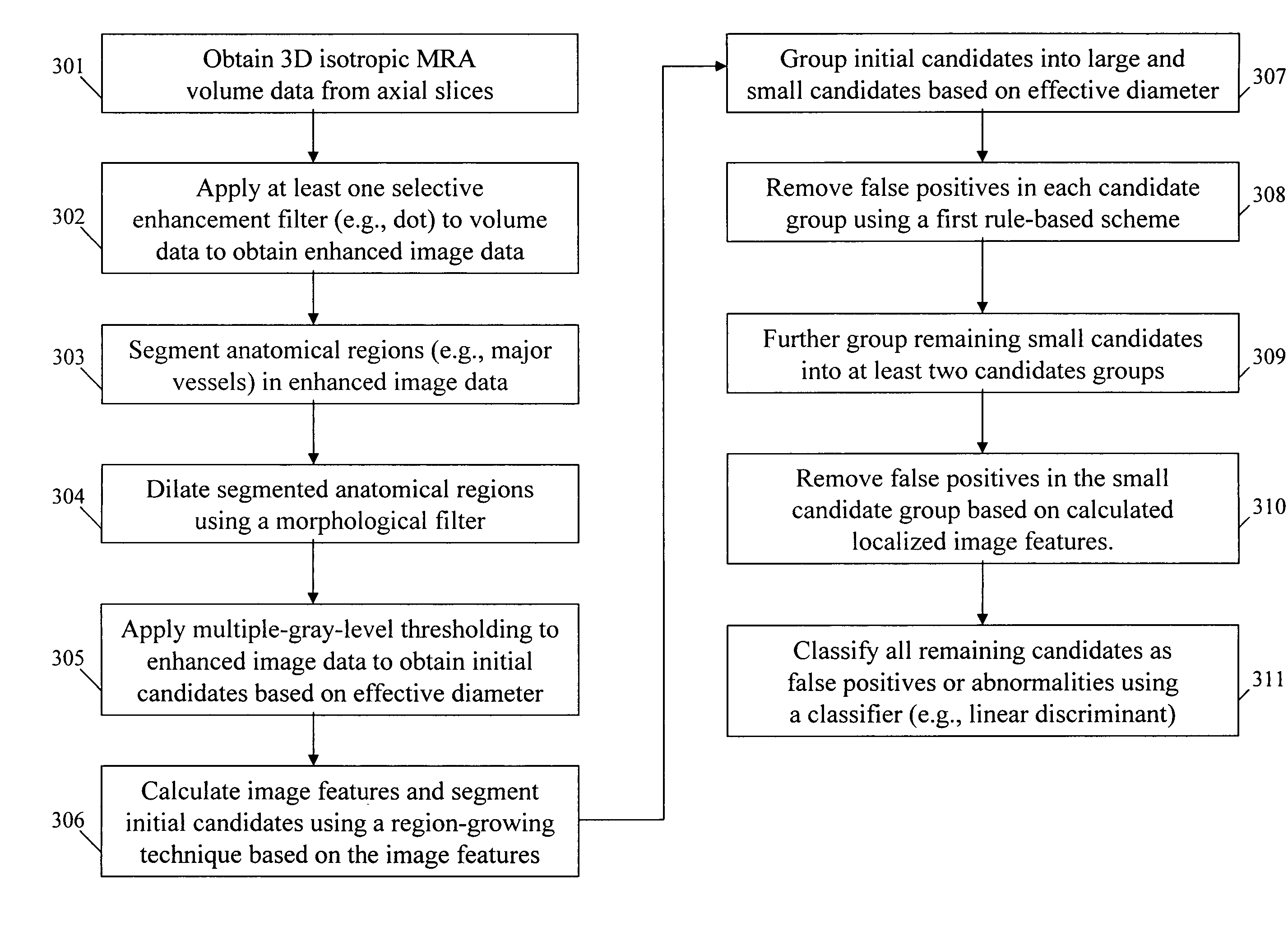
[0071]FIG. 3 shows a method for the detection of abnormalities in medical images according to an embodiment of the present invention.

[0072] In step 301, three-dimensional isotropic volume data is obtained from a plurality of axial MRA images. For example, each axial image could be 512×512 pixels with a pixel size of 0.391 mm and 128 slices having a slice thickness of 0.5 mm. Then, all original 3 D MRA images would be converted to isotropic volume data by use of linear interpolation and / or cropping such that the volume data was 400×400×128 voxels with a voxel size of 0.5 mm.

[0073] In step 302, at least one selective enhancement filter is applied to the isotropic volume data to enhance objects having specific shapes. For example, because some aneurysms are round protrusions and others are balloon-like objects, which appear on intracranial vessels, many aneurysm shapes were hemispherical or spherical. Therefore, in order to enhance aneurysms and suppress other objects such as vessels...


PUM


Abstract

A method, system, and computer program product for determining existence of an abnormality in a medical image, including (1) obtaining volume image data corresponding to the medical image; (2) filtering the volume image data using an enhancement filter to produce a filtered image in which a predetermined pattern is enhanced; (3) detecting, in the filtered image, a first plurality of abnormality candidates using multiple gray-level thresholding; (4) grouping, based on size and local structures, the first plurality of abnormality candidates into a plurality of abnormality classes; (5) removing false positive candidates from each abnormality class based on class-specific image features to produce a second plurality of abnormality candidates; and (6) applying the at least one abnormality to a classifier and classifying each candidate in the second plurality of abnormality candidates as a false positive candidate or an abnormality.

Description

STATEMENT REGARDING FEDERALLY SPONSORED RESEARCH [0001] The present invention was made in part with U.S. Government support under USPHS Grant Nos. CA62625 and CA98119. The U.S. Government may have certain rights to this invention.BACKGROUND OF THE INVENTION [0002] Field of the Invention [0003] The present invention relates generally to the automated detection of structures and assessment of abnormalities in medical images, and more particularly to methods, systems, and computer program products for the detection of intercranial aneurysm in medical images (such as MRA images) using selective enhancement filters. [0004] The present invention also generally relates to computerized techniques for automated analysis of digital images, for example, as disclosed in one or more of U.S. Pat. Nos. 4,839,807; 4,841,555; 4,851,984; 4,875,165; 4,907,156; 4,918,534; 5,072,384; 5,133,020; 5,150,292; 5,224,177; 5,289,374; 5,319,549; 5,343,390; 5,359,513; 5,452,367; 5,463,548; 5,491,627; 5,537,485; ...

Claims


Application Information

Patent Timeline
Patent Type & Authority Applications(United States)
IPC IPC(8): G06K9/00G06K9/40G06T5/00G06T5/30G06T7/00
CPCG06T7/0012G06T7/0091G06T2207/10072G06T2207/20044G06T2207/30101G06T5/003G06T7/0081G06T2207/20164G06T7/11G06T7/155G06T5/73
Inventor ARIMURA, HIDETAKALI, QIANGDOI, KUNIO
Owner UNIVERSITY OF CHICAGO
Learn More