Method of achieving high pretilt angles in a lilquid crystal cell

a liquid crystal cell and high pretilt angle technology, applied in the direction of thin material processing, instruments, coatings, etc., can solve the problems of difficult to obtain large values of (0) from 10°-80°, and all of these methods are, however, impractical for mass production

Inactive Publication Date: 2005-11-24
THE HONG KONG UNIV OF SCI & TECH
View PDF9 Cites 24 Cited by
  • Summary
  • Abstract
  • Description
  • Claims
  • Application Information

AI Technical Summary

Problems solved by technology

In particular, it is very difficult to obtain large values of θ(0) from 10°-80°.
All of these methods are, however, impractical for mass production.

Method used


Image

  • Method of achieving high pretilt angles in a lilquid crystal cell
  • Method of achieving high pretilt angles in a lilquid crystal cell
  • Method of achieving high pretilt angles in a lilquid crystal cell

Examples


Embodiment Construction

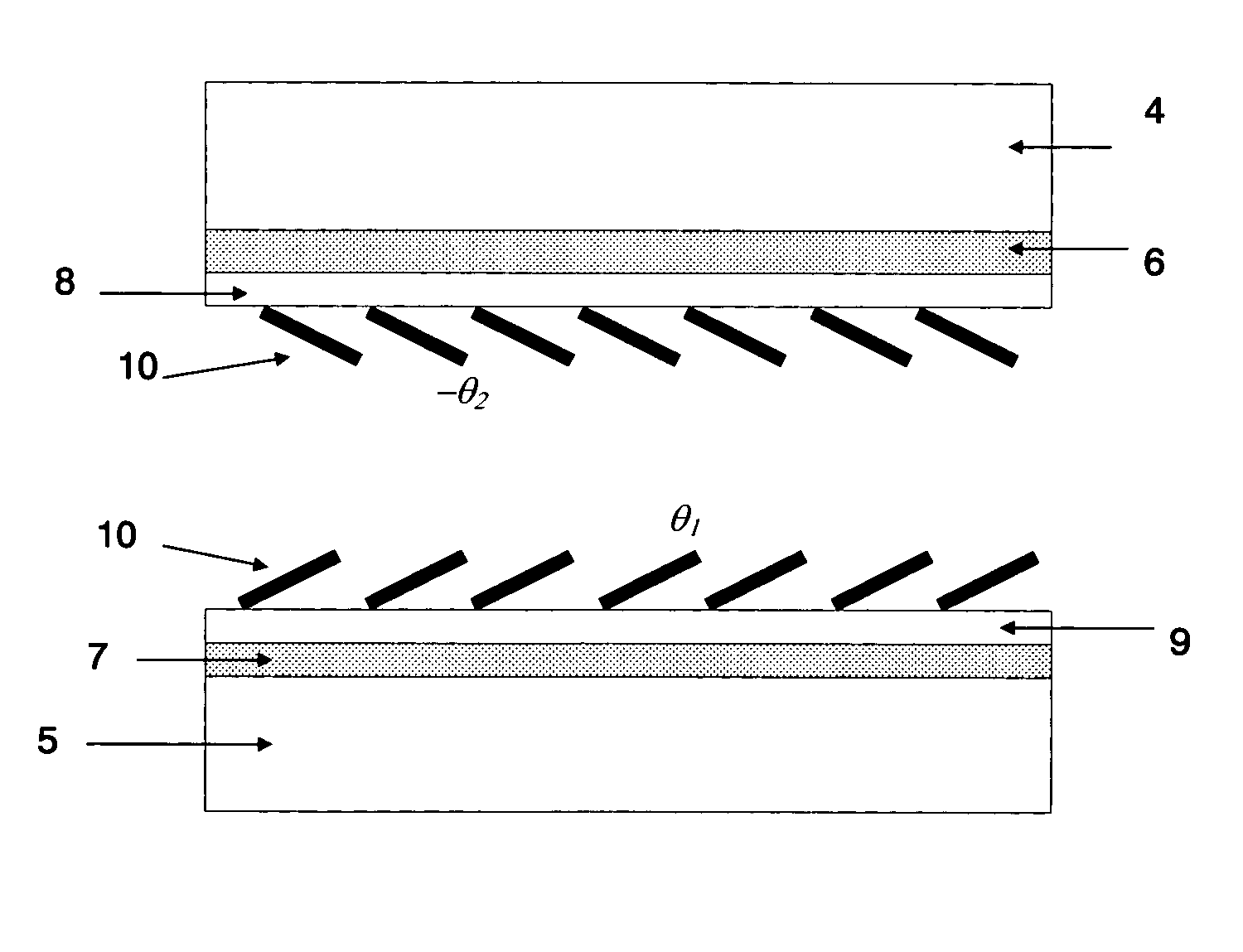
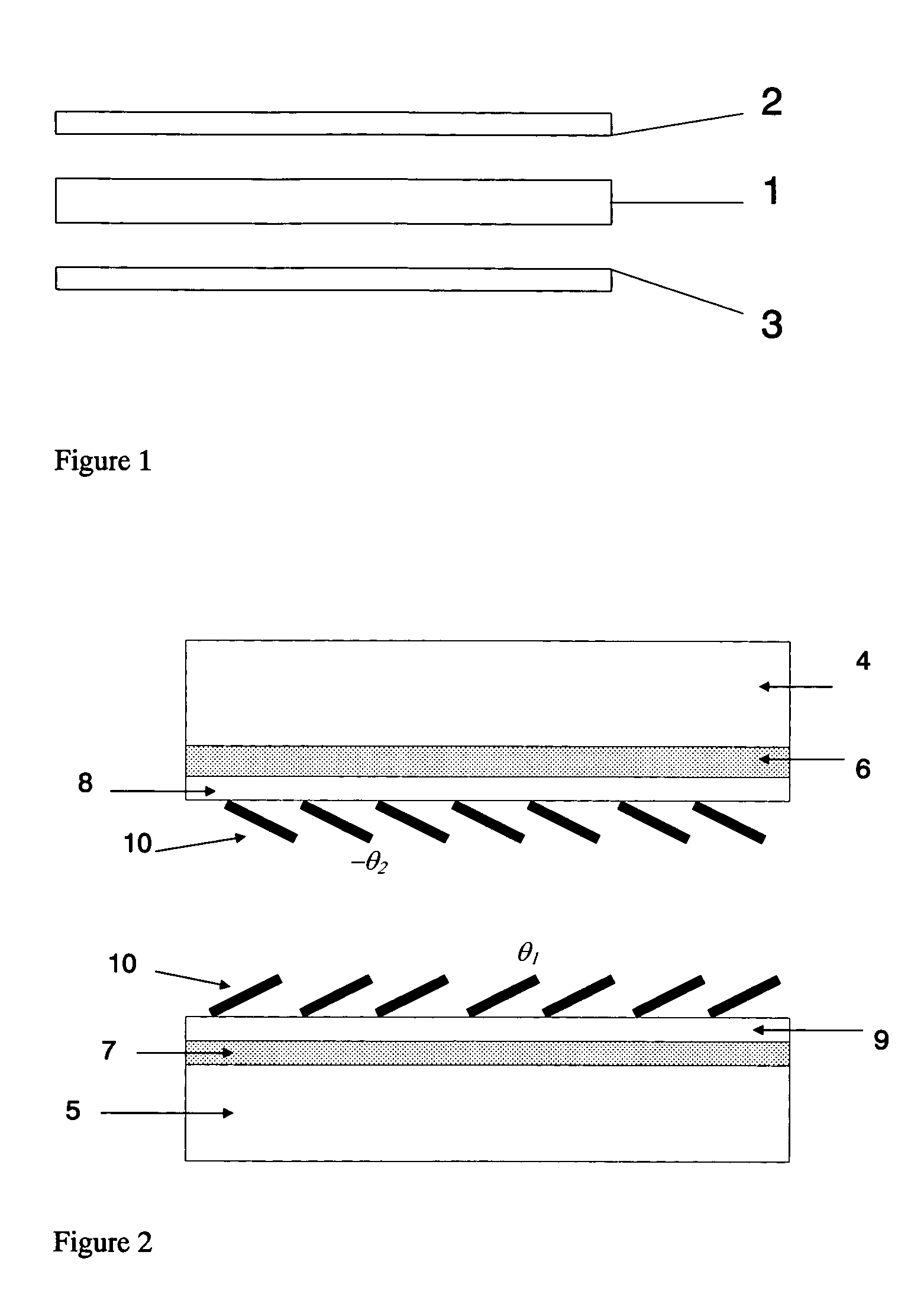
[0014] A liquid crystal display is usually made of a liquid crystal cell 1 and two polarizers 2, 3. The simplest liquid crystal cell is composed of top and bottom glass plates 4, 5, transparent conductive electrodes 6, 7, alignment layers 8, 9 and the liquid crystal layer 10. The angles of the liquid crystal layer on the contact surfaces with the alignment layers are called the pretilt angles. As shown in FIG. 2, the pretilt angles on the top and bottom layers can be different. The transmission or reflectance of light by the liquid crystal cell is determined completely by knowing the polarizer angles α and γ, and the alignment condition of the liquid crystal layer 10. The liquid crystal layer is defined completely by the tilt angle θ(z) and twist angle φ(z) distributions of the liquid crystal director vector n as a function of its position in the one-dimensional case, and θ(x,y,z) and φ(x,y,z) in the three-dimensional case.

[0015] The electrodes 6, 7 and the alignment layers 8, 9 ar...


PUM

PropertyMeasurementUnit
thicknessaaaaaaaaaa
thicknessaaaaaaaaaa
pretilt anglesaaaaaaaaaa

Abstract

A new method of obtaining high pretilt angles of predetermined values in a liquid crystal cell is disclosed. Appropriate amounts of compatible homogeneous and homeotropic alignment materials are mixed with special treatment methods to achieve the desired results.

Description

FIELD OF THE INVENTION [0001] This invention relates to method of producing a high pretilt angle in a liquid crystal cell that can be controlled reliably and more specifically relates to a method enabling pretilt angles from 10 to 80 degrees to be achieved. BACKGROUND OF THE INVENTION [0002] A liquid crystal display consists, among many other things, of a liquid crystal layer. The alignment behavior of this liquid crystal layer determines most of the optical properties of the liquid crystal display. This alignment is determined by the alignment layers in contact with the liquid crystal layer itself. The most common form of this alignment layer is a thin film of polyimide deposited on the glass substrate. The preparation conditions of these top and bottom alignment layers provide an alignment direction as well as a pretilt angle for the liquid crystal molecules near the surface of the liquid crystal layer. [0003] The pretilt angles achievable with common polyimides are predetermined ...

Claims


Application Information

Patent Timeline
Patent Type & Authority Applications(United States)
IPC IPC(8): B05D5/06B05D5/12G02F1/1337G02F1/139
CPCG02F1/133711Y10T428/1005G02F2001/133761G02F1/13378C09K2323/02G02F1/133761Y10T428/31721
Inventor KWOK, HOI SINGYEUNG, FION SZE YANXIE, FENGCHAOTSUI, OPHELIA KWAN CHUISHENG, PING
Owner THE HONG KONG UNIV OF SCI & TECH
Why Eureka
Try Eureka