Polishing fixture for simultaneous loading of a plurality of optical connectors and fiber stubs and a method of loading

Inactive Publication Date: 2005-11-24
SAGITTA ENG SOLUTIONS
View PDF11 Cites 2 Cited by
  • Summary
  • Abstract
  • Description
  • Claims
  • Application Information

AI Technical Summary

Benefits of technology

[0040] The present invention significantly reduces the time required for loading a polishing fixture with a plurality of connectors or ferrules to be polished and accordingly reduces the polishing costs.
[0041] Connectors or fiber stubs loaded in a polishing fixture for polishing have a uniform projection (protrusion) length that does not depend on the ferrule within connector housing position. The polishing force is equally distributed between the connectors or fiber st

Problems solved by technology

Polishing of an optical connector on a piece-by-piece basis is not practical due to the nature of the process as well as the mix of the quantities and the structure of the connectors to be polished.
Loading of a large number of the connectors on a one-by-one basis is a time consuming operation that to some extent reduces the throughput of a polishing system and requires additional labor increasing the cost of the polished connectors.
Loading of fiber stubs in a polishing fixture is even more complicated.
The operation is time consuming and error prone.
Polishing fixtures are not versatile enough to adopt the v

Method used


Image

  • Polishing fixture for simultaneous loading of a plurality of optical connectors and fiber stubs and a method of loading
  • Polishing fixture for simultaneous loading of a plurality of optical connectors and fiber stubs and a method of loading
  • Polishing fixture for simultaneous loading of a plurality of optical connectors and fiber stubs and a method of loading

Examples


Example

[0067] The principles and execution of a method according to the present invention, and the operation and properties of the fixture, loading plate, fiber stub insertion tool and fiber stub inversion assembly described thereby may be understood with reference to the drawings, wherein like reference numerals denote like elements through the several views and the accompanying description of non-limiting, exemplary embodiments.

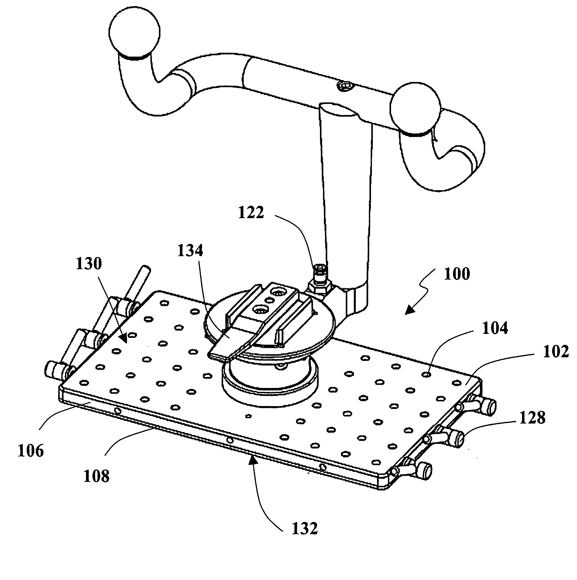
[0068] Reference is now made to FIGS. 2, 3 and 4 that illustrate an exemplary embodiment of the fixture for simultaneously clamping a plurality of optical fiber ferrules or fiber stubs for polishing of the present invention. Polishing fixture 100 optionally and preferably includes a plate assembly 106 having an upper surface 130, a lower surface 132 and a plurality of ferrule-receiving bores 104 disposed across the upper surface and extending from upper surface 130 to lower surface 132, each ferrule-receiving bore 104 for receiving a ferrule 138 (FIG. 4). Fixture...


PUM

PropertyMeasurementUnit
Diameteraaaaaaaaaa

Abstract

A fixture for simultaneously clamping a number of optical fiber ferrules or fiber stubs for polishing. The fixture includes a plate assembly with an upper surface, a lower surface and a number of ferrule-receiving bores disposed across the upper surface and extending from the upper surface to the lower surface, each ferrule-receiving bore for receiving a ferrule. The fixture further includes a number of ferrule gripper arrangements, each associated with one of the ferrule-receiving bores, each of the ferrule gripper arrangements being selectively deployable between a released state for insertion of a ferrule into the ferrule-receiving bore and a gripping state in which the gripper arrangement clamps a ferrule within the ferrule-receiving bore. The fixture also includes a locking mechanism associated with at least a group of the number of ferrule gripper arrangements and configured to deploy the group of ferrule gripper arrangements substantially simultaneously from the released state to the gripping state so as to clamp substantially simultaneously a number of optical fiber ferrules located within a corresponding group of the ferrule-receiving bores.

Description

FIELD OF THE INVENTION [0001] The present invention relates to the field of polishing of connectors and fiber stubs. More particularly the present invention relates to a polishing fixture and a method for simultaneous loading, reloading and polishing a plurality of fiber stubs or optical connectors. BACKGROUND OF THE INVENTION [0002] With the growth of optical communication networks there is a growing need for altering the network configuration, connecting to it new nodes and devices, disconnecting old devices and maintaining the network. These connections are easy and convenient to make with the help of an optical connector, which is a demountable device for attaching an optical fiber to another optical fiber, or to an active or passive device. [0003] The losses of the optical signal power at each connection depend on the geometry of the connector end-face, matching surfaces geometry, surface quality and other parameters. In order to reduce optical signal power coupling losses, the...

Claims


Application Information

Patent Timeline
IPC IPC(8): B24B1/00B24B19/22B24B41/06G02B6/38
CPCB24B19/226G02B6/3863B24B41/067
Inventor GAZIT, RAMISARFATY, ORIKLUP, GUYHACHONOCHI, DANIEL
Owner SAGITTA ENG SOLUTIONS
Why Eureka
Try Eureka