Method and apparatus for detecting and identifying firearms

a technology for identifying firearms and detecting methods, applied in the direction of weapons, ammunition loading, weapon components, etc., can solve the problems of high cost and relatively slow operation of present systems for conducting such searches, including x-ray systems and the like, and achieve the effect of convenient position for placing the chip

Inactive Publication Date: 2005-12-01
LESLIE DENNIS
View PDF10 Cites 66 Cited by
  • Summary
  • Abstract
  • Description
  • Claims
  • Application Information

AI Technical Summary

Benefits of technology

[0013] If the firearm is made of a nonferromagnetic material or has a nonferromagnetic section such as a butt or handle, the cavity for the chips may be formed directly in this nonferromagnetic section. Weapons which are made from steel typically have wood or plastic handgrips, and this affords a convenient position in which to place the chip. In the cases of weapons made entirely from ferromagnetic materials, a cavity in the weapon may be lined with a radiofrequency-absorbing elastomer or other radiofrequency-absorbing material to shield the chip from fields which might be induced through the ferromagnetic sections.

Problems solved by technology

Present systems for conducting such searches, including x-ray systems and the like, are extremely expensive and relatively slow in operation.

Method used


Image

  • Method and apparatus for detecting and identifying firearms
  • Method and apparatus for detecting and identifying firearms
  • Method and apparatus for detecting and identifying firearms

Examples


Embodiment Construction

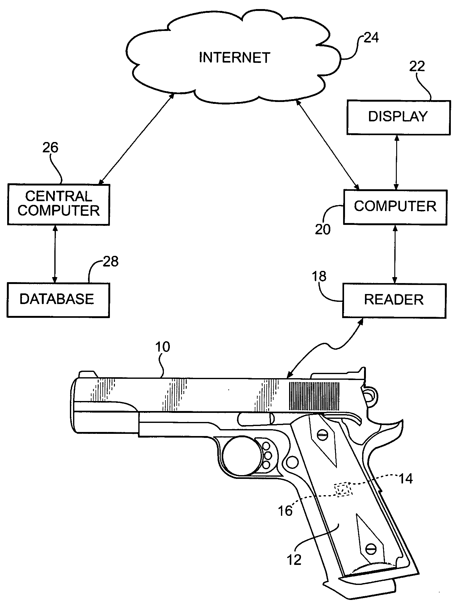
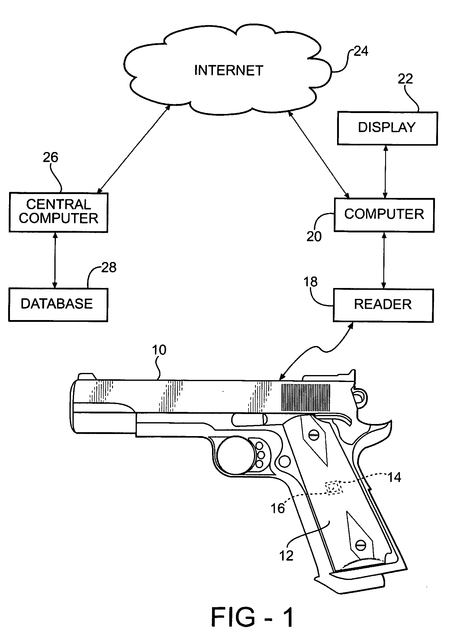
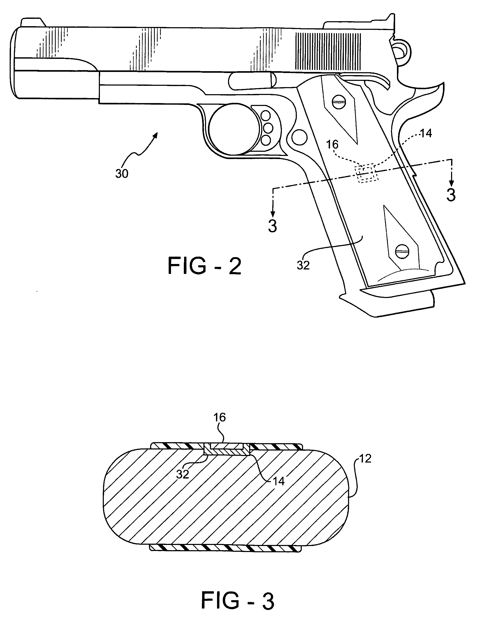
[0020] Referring to the drawings, a typical system employing the method of the present invention is illustrated in FIG. 1. A handgun 10 having a handgrip 12 is conventional except for the formation of a socket 14 which constitutes a recess in the surface of the handgrip. The socket supports an RFID chip 16 which is programmed to retain the serial number of the handgun as assigned during its manufacture or later retrofit. The RFID chip is preferably of the digital, passive type typically employed with shipment containers. The RFID chip is of relatively small dimensions, such as one or two centimeters, and of a thickness of a fraction of a centimeter. The cavity 14 has sufficient thickness so that the surface of the chip does not extend into the grip area. It may be covered in such a way as to be substantially invisible.

[0021] A reader 18 for the RFID chip 16 is capable of sending an interrogating signal to the chip from a substantial distance such as in excess of fifty feet away. Im...


PUM


Abstract

A system for detecting the presence of firearms and identifying their unique status includes a radiofrequency identification chip supported within each firearm either by the manufacturer or by later retrofit. The RFID chip stores the unique serial number for the firearm, preferably in nonvolatile form. A reader for the chips may be used to transmit an interrogating signal from a distance which causes the chip to send a responsive signal including its serial number. The reader picks up the serial number and provides it to an associated computer. The serial number so obtained may be used with databases to maintain inventories of firearms or determine the history of firearms.

Description

RELATED APPLICATION [0001] This application claims priority of U.S. Provisional Patent Application Ser. No. 60 / 549,128 filed Mar. 1, 2004, which is incorporated herein by reference.FIELD OF THE INVENTION [0002] This invention relates to a system for remotely detecting the presence of a firearm and identifying the serial number of the firearm employing radiofrequency identification (RFID) tags embedded in firearms and remote readers for the RFID tags. BACKGROUND OF THE INVENTION [0003] There are many situations in which it is desirable to have the ability to detect the presence of a firearm from a distance and, in certain situations, to determine a serial number assigned to the firearm. For example, when police officers approach a parked vehicle it is often of importance for them to know whether a firearm is contained in the vehicle. The officers' approach to the situation can be critically dependent upon this knowledge. Similarly, it is common practice to screen persons entering pub...

Claims


Application Information

Patent Timeline
Patent Type & Authority Applications(United States)
IPC IPC(8): F41A9/53F41A17/00
CPCF41A17/063F41A17/00
Inventor LESLIE, DENNIS
Owner LESLIE DENNIS
Why Eureka
Try Eureka