Oil-feeding device for engine crankshaft

a technology of oil-feeding device and crankshaft, which is applied in the direction of crankshafts, machines/engines, auxilaries, etc., can solve the problems of increasing the size of the oil pump, drive loss, cost-up and difficulty in mounting the device on a vehicle, and the crankshaft of a v-type engine oil-feeding device cannot be used, so as to reduce the amount of lubricating oil leaking and increase the friction of the bearing member

Inactive Publication Date: 2005-12-01
TAIHO INDUSTRIES CO LTD
View PDF4 Cites 35 Cited by
  • Summary
  • Abstract
  • Description
  • Claims
  • Application Information

AI Technical Summary

Benefits of technology

[0009] The present invention is made while taking into account the aforementioned problems of a conventional oil-feeding device of a crankshaft in which device at least one of paired bearing members supporting a main journal portion of a crankshaft has a half-circumferential slot and lubricating oil is fed to a surface of a pin portion through a pin oil-feeding passage from the half-circumferential slot. A main object of the present invention is to reduce an amount of lubricating oil leaking from an area supporting a main journal portion by limiting the extending area of a circumferential slot of a bearing member without increasing friction of the bearing member against the main journal portion.
[0012] According to the structure of the first paired bearing members, one of the paired substantially half-cylindrical bearing members, mutually cooperating to support the main journal portion of the crankshaft, has the oil groove formed in a surface facing the main journal portion, communicating to the oil passage of the cylinder block and extending circumferentially, which oil groove does not extend in the crush relieves, and therefore, the amount of lubricant oil, fed from an oil passage in the block to the oil groove of one of the bearing members and leaking from the oil groove to the area of the crush relieves, can be surely reduced, in comparison with a case of a conventional oil-feeding device in which an oil groove extends also to the crush relieves. Further, since the amount of lubricant oil, leaking from the oil groove to the area of the crush relieves, can be surely reduced, an enough amount of lubricant oil can be fed to the pin portions of the crankshaft if it has the pin oil-feeding passages feeding lubricant oil to the pin portions of the crankshaft from the oil groove, and therefore, in comparison with conventional oil-feeding devices, the size of an oil pump can be smaller; drive loss and cost will be reduced; and the mounting of the oil pump on a vehicle become easier.
[0013] Moreover, according to the structure of the above-mentioned crankshaft oil-feeding device, the first main journal portion is supported with the first paired bearing members; the second main journal portion is supported with the paired substantially half-cylindrical bearing members having no oil groove; the crankshaft has the internal oil passage extended from the surface of the first main journal portion to the surfaces of the pin portions on the opposite sides of the first main journal portion; and the internal oil passage communicates with the oil groove of one of the bearing members at least one time during one revolution of the crankshaft. Thus, lubricating oil can be certainly fed to the pin portions on the opposite sides of the first main journal portion through the internal oil passage from the oil groove of one of the bearing members of the first main journal, and, since the paired bearing members supporting the second main journal portion have no oil groove, the amount of lubricating oil, leaking from the paired bearing members supporting the second main journal portion, can be reduced certainly.

Problems solved by technology

Moreover, in a conventional oil-feeding device for a crankshaft, when lubricating oil is fed to pin portions of the crankshaft through the pin oil-feeding passages at an enough amount, irrespective of the aforementioned leakage of lubricating oil from the main journal, the increase in size of an oil pump will be inevitable, causing problems of a drive loss, cost-up and difficulty in mounting the device on a vehicle.
This oil-feeding device cannot be used for a crankshaft of a V-type engine which has two pin oil-feeding passages connecting from one main journal to two pin portions on the opposite sides of the journal.

Method used


Image

  • Oil-feeding device for engine crankshaft
  • Oil-feeding device for engine crankshaft
  • Oil-feeding device for engine crankshaft

Examples


first embodiment

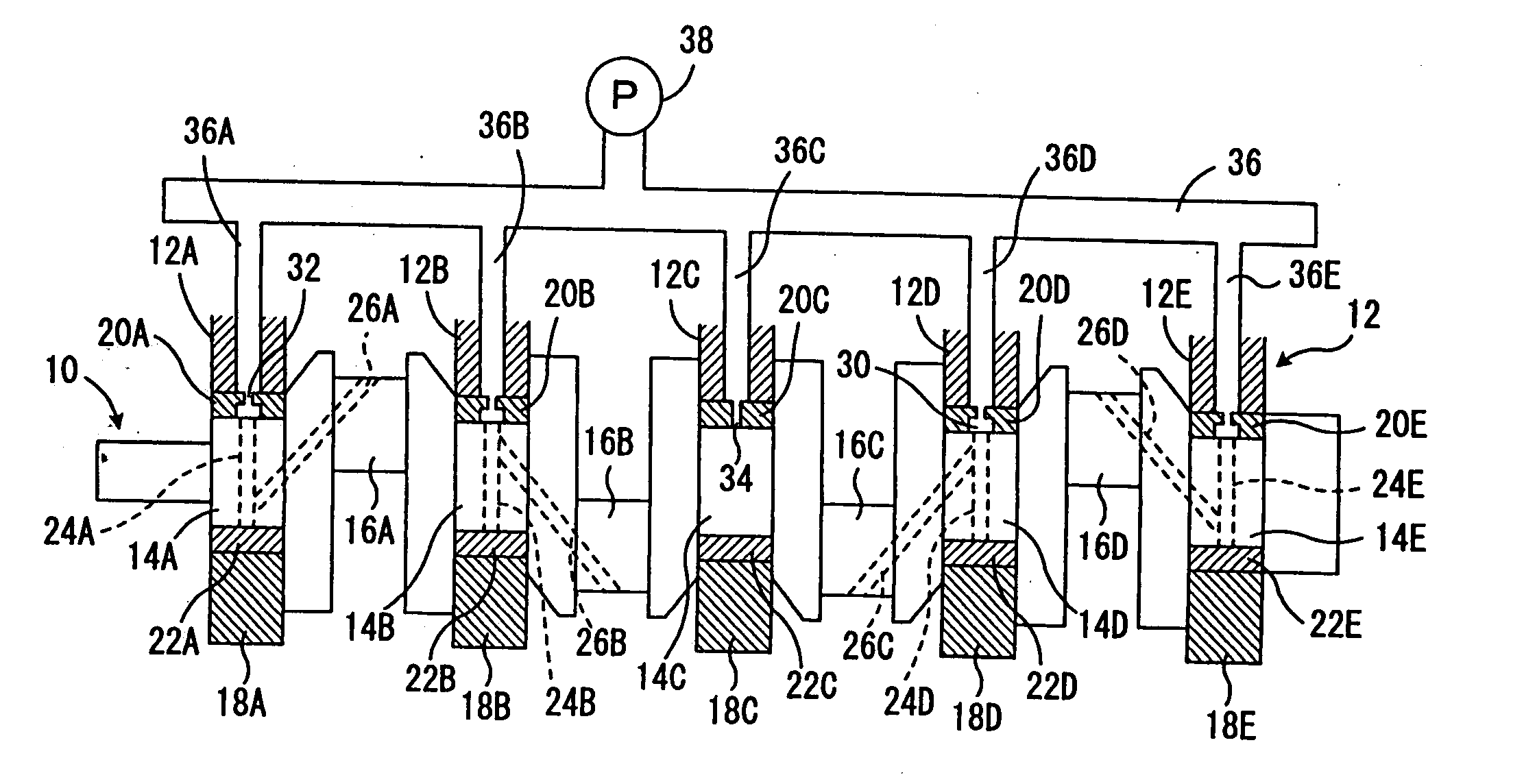
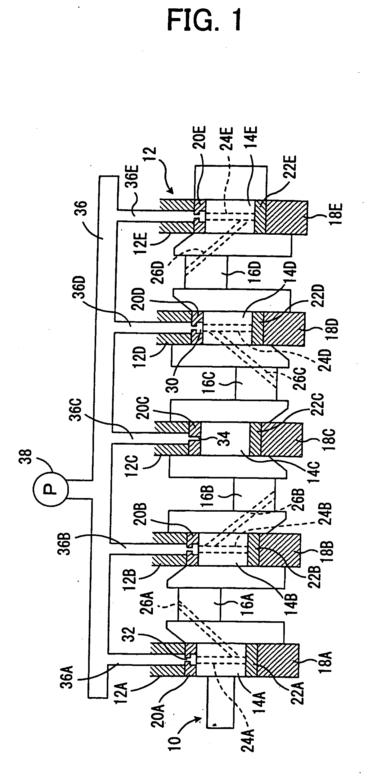
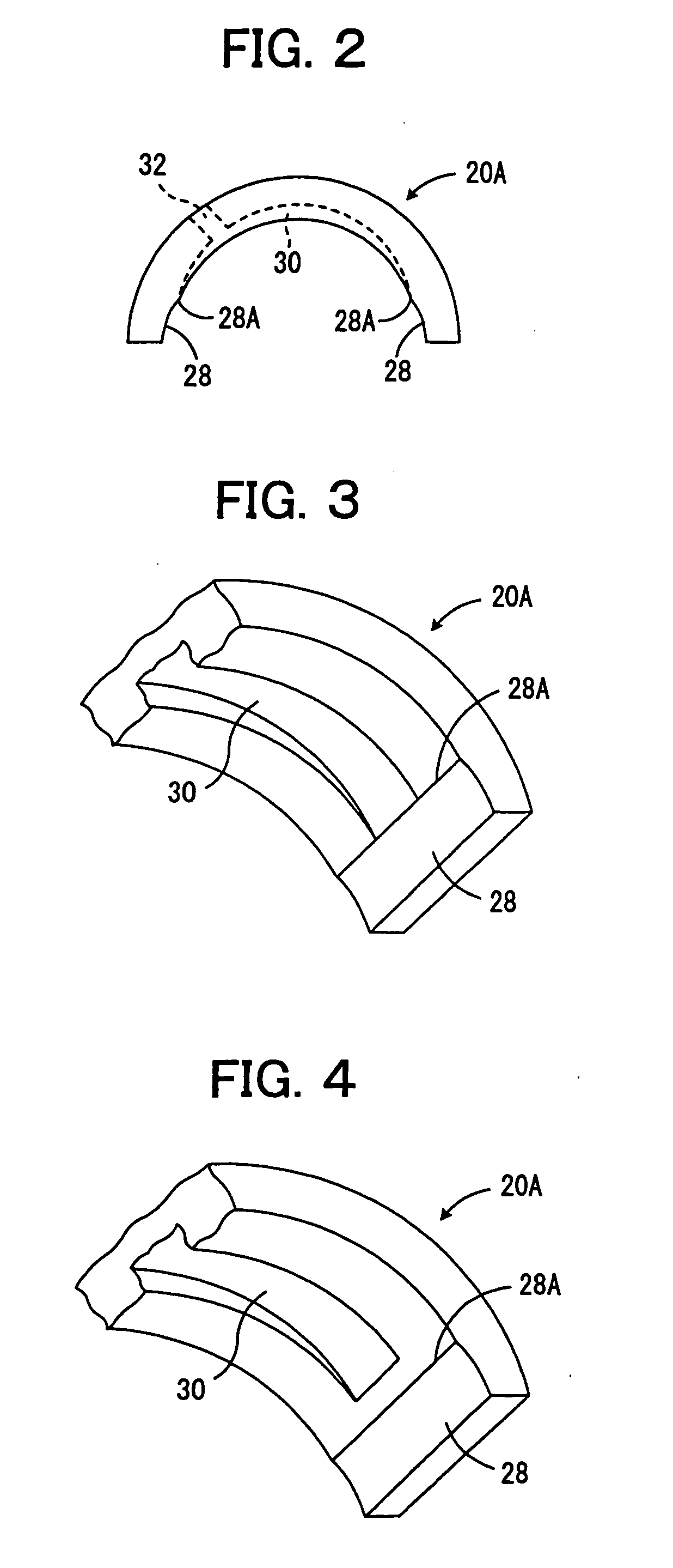
[0029]FIG. 1 is a diagrammatic view showing a structure of a first embodiment of an oil-feeding device of a crankshaft according to the present invention, applied to an in-line four-cylinder gasoline engine; FIG. 2 is a side view showing one of the upper bearing members shown in FIG. 1; and FIG. 3 is an enlarged partial perspective view showing an end of the upper bearing member shown in FIG. 2.

[0030] In FIG. 1, the reference numeral 10 shows an engine crankshaft, which is rotatably supported by five supporting portions 12A-12E of a cylinder block 12. The crankshaft 10 has five main journal portions 14A-14E and four pin portions 16A-16D, which are located between the main journal portions, offset radially therefrom and circumferentially relative to one another around the axis, and the main journal portions 14A-14E and pin portions 16A-16D are integrally connected to one another with arm portions.

[0031] Caps 18A-18E each are fixed to the lower ends of the supporting portions 12A-12...

second embodiment

[0043]FIG. 5 is a diagrammatic view of a structure showing a second embodiment of an oil-feeding device of a crankshaft according to the present invention, applied to an in-line four cylinder gasoline engine. In FIG. 5, the same parts as in FIG. 1 are designated by the same reference numerals as in FIG. 1.

[0044] In this second embodiment, as in the main journal portion 14C in the above-mentioned first embodiment, no through passage is formed in the main journal portions 14A, 14C and 14E. Further, as in the upper bearing member 20C of the main journal portion 14C in the first embodiment, no oil groove 30 is formed in the upper bearing members 20A, 20C and 20E of main journal portions 14A, 14C and 14E, but, communicating pores 34 are formed therein.

[0045] Moreover, the end of the pin oil-feeding passage 26A is connected to the end of the through passage 24B opposite to its end to which the end of the pin oil-feeding passage 26B is connected. The end of the pin oil-feeding passage 26...


PUM


Abstract

An oil-feeding device for a crankshaft where the amount of lubricant oil leaking from supporting areas of main journal portions is reduced without increasing friction of bearing members against the main journal portions. The oil-feeding device for a crankshaft includes upper bearing members and lower bearing members. The upper and lower bearing members have a half hollow cylindrical shape, are provided with crush relief portions at both ends, and jointly encompass main journal portions of a crank shaft. The upper bearing members have circumferentially extending oil grooves provided in the faces opposite the main journal portions, the grooves penetrating through oil passages of a cylinder block. The lower bearing members do not have oil grooves. The oil grooves do not extend in the crush relief portions, and therefore the leakage of lubricant oil, fed to the oil grooves, to the areas of the crush relief portions is suppressed.

Description

TECHNICAL FIELD [0001] The present invention relates to an engine crankshaft, and more specifically, to an oil-feeding device of a crankshaft. BACKGROUND ART [0002] An oil-feeding device of a crankshaft of an engine mounted on a vehicle, such as automobile, which has been already known as one of an oil-feeding device as described in Japanese Patent Laid-Open Publication No. 7-27127, is designed to comprise a pair of half-cylindrical bearing members mutually cooperating to surround a main journal portion of a crankshaft, wherein each of the bearing members has a half-circumferential slot provided on its surface facing the main journal portion and communicating with an oil passage of a cylinder block, and the crankshaft has paired pin oil-feeding passages each opening to the main journal portion on one end and a surface of a pin portion on the other end, whereby, whenever the crankshaft is half-rotated, the paired pin oil-feeding passages are made communicate alternative one of the ha...

Claims


Application Information

Patent Timeline
Patent Type & Authority Applications(United States)
IPC IPC(8): F01M1/06F01M11/02F16C3/14F16C9/02F16C33/10
CPCF01M1/06F01M11/02F01M2011/026F16C17/022F16C9/02F16C33/1065F16C3/14F16C2360/22F16C17/26F16C33/046F16C33/1055
Inventor TERADA, TATSUHIROKANOH, TOMOHIROHIKITA, YASUHIROYAMAZAKI, MASAO
Owner TAIHO INDUSTRIES CO LTD
Why Eureka
Try Eureka