Heat sink mounting device

a technology for mounting devices and heat sinks, which is applied in the direction of coupling device connections, semiconductor/solid-state device details, instruments, etc., can solve the problems of inconvenient mounting, unnecessary attachment and detachment of clips, and increased need for large and heavier heat sinks. achieve the effect of convenient mounting

Inactive Publication Date: 2005-12-01
HON HAI PRECISION IND CO LTD +1
View PDF17 Cites 11 Cited by
  • Summary
  • Abstract
  • Description
  • Claims
  • Application Information

AI Technical Summary

Benefits of technology

[0004] Accordingly, an object of the present invention is to provide a mounting device which can conveniently mount a heat sink to a heat generating unit.

Problems solved by technology

Therefore, larger and heavier heat sinks are becoming increasingly necessary to efficiently remove the heat from the electronic units.
However, securing of the clip requires a tool.
Attachment and detachment of the clip are unduly laborious and time-consuming.

Method used


Image

  • Heat sink mounting device
  • Heat sink mounting device
  • Heat sink mounting device

Examples


Embodiment Construction

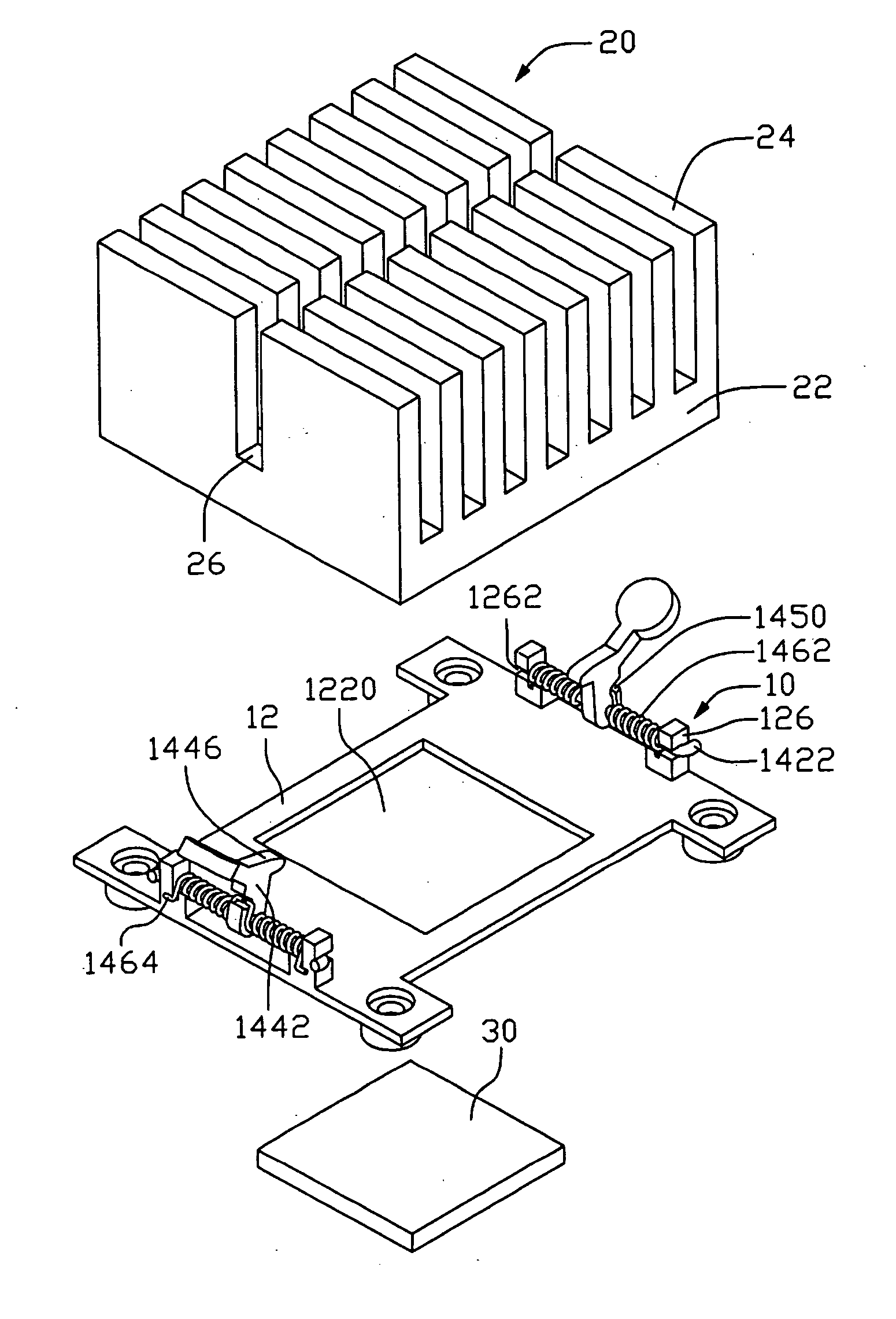
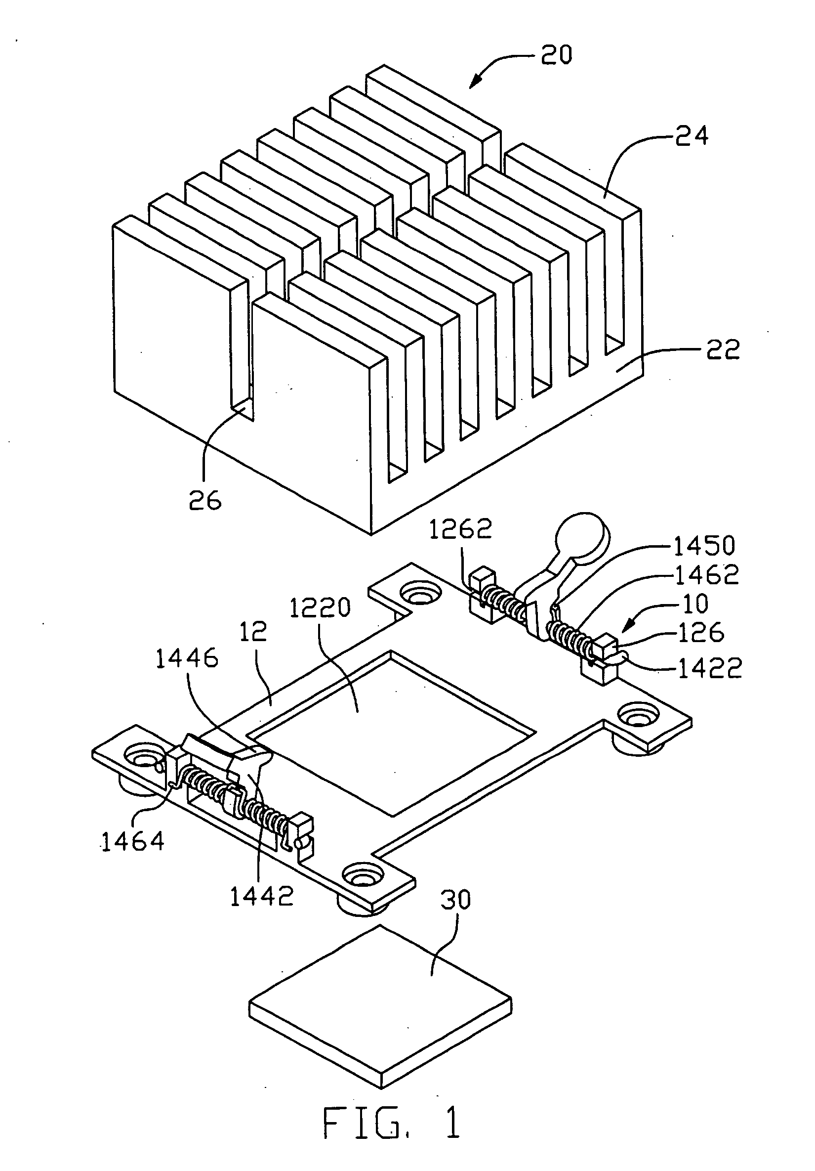
[0011] Referring to FIG. 1, a mounting device 10 in accordance with a preferred embodiment of the present invention for mounting a heat sink 20 to an electronic unit 30 is shown. The heat sink 20 comprises a base 22 and a plurality of parallel fins 24 extending from the base 22. The heat sink 20 defines a channel 26 crossing through the middle of the fins 24.

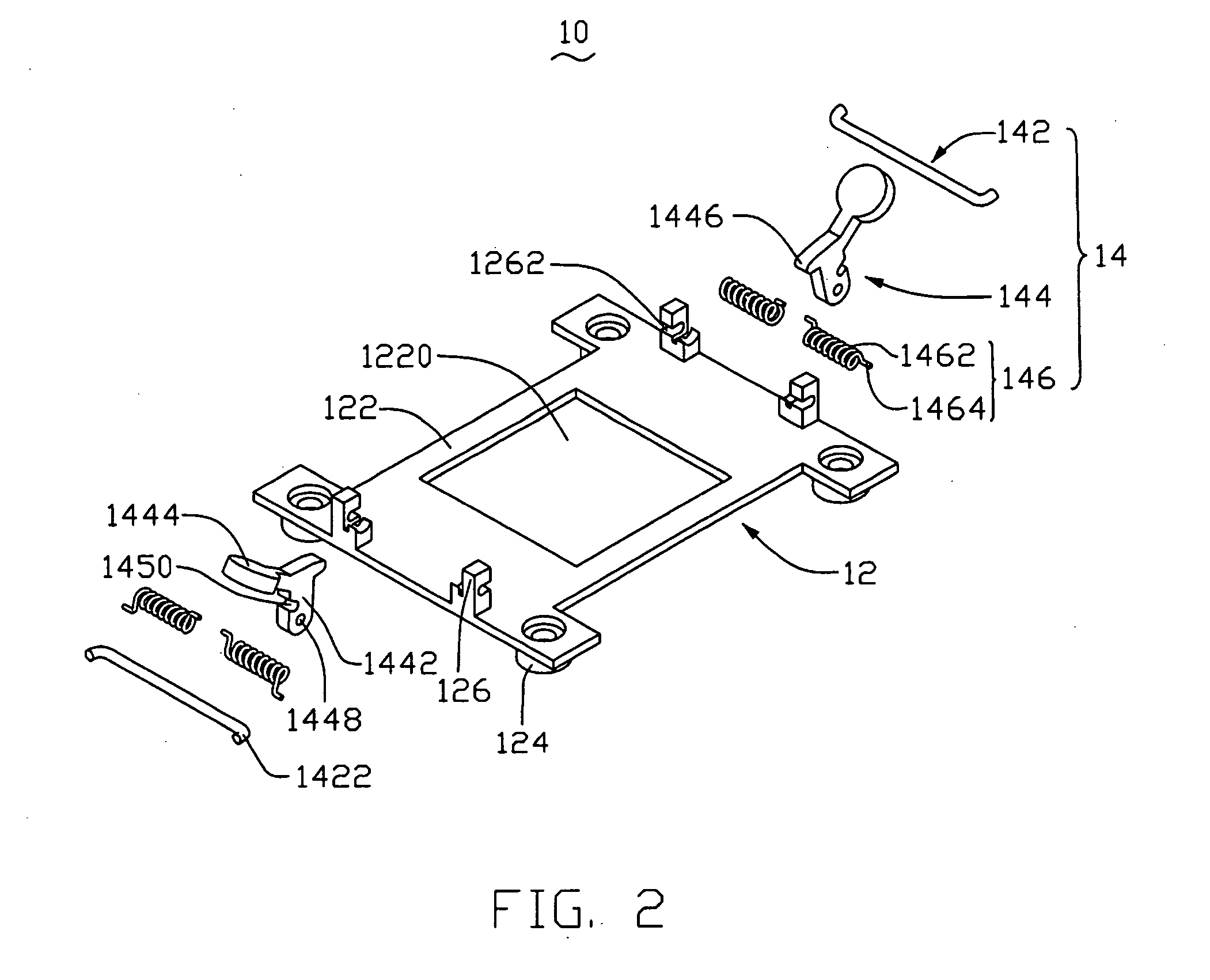
[0012] Referring also to FIG. 2, the mounting device 10 comprises a basis 12 for being attached to a printed circuit board (not shown), and two operating bodies 14 respectively installed on opposite sides of the basis 12.

[0013] The basis 12 comprises a quadrate plate 122. The plate 122 defines an opening 1220 for receiving the electronic unit 30. Each corner of the plate 122 extends downwardly to form a column 124. The basis 12 is for being mounted on the printed circuit board by screws (not shown) locked in the columns 124. Two pairs of apart supporting members 126 extend upwardly from opposite sides of the plate 122. Each su...


PUM

PropertyMeasurementUnit
forceaaaaaaaaaa
angleaaaaaaaaaa
timeaaaaaaaaaa

Abstract

A mounting device for a heat sink includes a basis and a pair of operating bodies. Two pair of supporting members are provided on opposite sides of the basis. The operating body includes a pole connecting the supporting members, a pivot member pivotably attached to the pole, and at least a spring member encircling the pole. The pivot member includes a pressing portion adapted for pressing the heat sink. One end of the spring member is fixed on one of the supporting members, and the other end of the spring member is secured with the pivot member. The pivot member is pivotable from a first position to a second position under action of a force and returns back to the first position from the second position under action of the spring member after withdrawing the force.

Description

TECHNICAL FIELD [0001] The present invention relates to mounting devices, and particularly to a mounting device for readily mounting a heat sink to a heat generating unit. BACKGROUND [0002] With the continuing development of computer electronics technology, new electronic units such as a central processing unit (CPU) can perform more and more functions. Heat generated by these modem electronic units has increased commensurately. Therefore, larger and heavier heat sinks are becoming increasingly necessary to efficiently remove the heat from the electronic units. Oftentimes, mounting devices are required for mounting the heat sinks to the electronic units. [0003] A clip is often used to mount a heat sink to an electronic unit. The clip is usually integrally formed from a metal sheet. A typical such clip is formed by bending the sheet to form a pressing body and a pair of latching arms extending from opposite ends of the pressing body. Each latching arm is bent with a suitable angle re...

Claims


Application Information

Patent Timeline
Patent Type & Authority Applications(United States)
IPC IPC(8): B21B37/58G06F1/20H01L23/34H01L23/40
CPCH01L23/4093H01L2924/0002H01L2924/00
Inventor CHEN, CHUN-CHIWU, YI-QIANGZHAO, LIANG-HUI
Owner HON HAI PRECISION IND CO LTD
Why Eureka
Try Eureka