
Linear ion trap apparatus and method utilizing an asymmetrical trapping field

a technology of ion trapping and asymmetrical trapping field, which is applied in the direction of mass spectrometer, separation process, stability-of-path spectrometer, etc., can solve the problem of outside the stability region, unstable ions of increasing m/z values, and inability to adequately control or focus the direction of ion ejection

Active Publication Date: 2005-12-01
AGILENT TECH INC
View PDF23 Cites 40 Cited by
  • Summary
  • Abstract
  • Description
  • Claims
  • Application Information

AI Technical Summary

Benefits of technology

[0035] The foregoing methods can be implemented in an electrode structure that is axially segmented into front, center, and rear sections. The various potentials and voltages can be applied to the electrode structure at one or more of these sections as appropriate for the procedure being implemented.
[0036] Structurally inherent multipole components can be designed into the electrode stru...

Problems solved by technology

An ion lying outside of a stability region is unstable, in which case the displacement of the ion grows without bounds and the ion is ejected from the trapping field; that is, the parameters of the trapping field for this particular ion are such that the ion cannot be trapped.
The amplitude of the RF voltage is then increased such that ions of increasing m / z values become unstable.
First, the direction of ion ejection cannot be adequately controlled or focused.
Nonetheless, this technique fails to eject all ions in a single desired direction.
In addition, the mechanical solution can add to the cost, complexity, and precision of the manufacturing process.
Moreover, the octopole field is mechanically fixed; its parameters cannot be changed.
When a buffer gas such as helium is used to dampen the ion trajectories to the center of the trap, parametric excitation is ineffectual due to the vanishing strength of the supplemental quadrupole field.
This mode of ion ejection is not optimal, however, when the trapping field amplitude is changing as is normally the case for mass scanning.
A disadvantage of the foregoing prior art techniques is that even if ion movement can be concentrated along a single axis to improve scanning the ions out from the trapping field, the ions are nevertheless equally likely to be ejected in either direction along the axis.
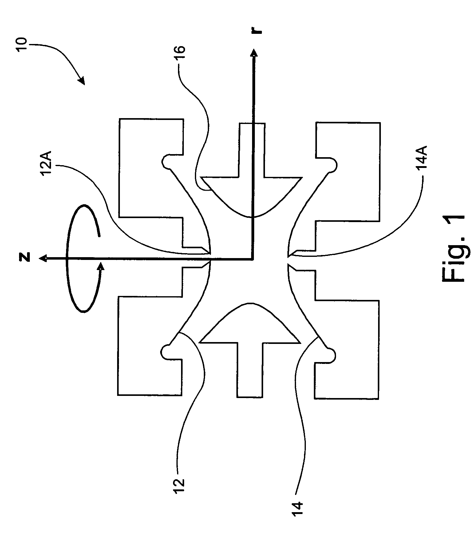
However, a three-dimensional trap structure 10 does not offer the advantages of a linear, two-dimensional trap structure as described below.
It is further known, however, that these nonlinear resonances degrade the performance of quadrupole mass filters.
By comparison, the only practicable way to increase the storage volume in the three-dimensional ion trap 10 in FIG. 1 is to increase the radial distance of the hyperbolic electrode surfaces from the center point of the volume, which undesirably increases the RF voltages required for operation.
In U.S. Pat. No. 5,420,425 to Bier et al., it was further suggested that increasing the ion storage volume by radially increasing the electrode spacing is disadvantageous because it decreases the m / z range of ions trappable in the volume.
As in the case of many three-dimensional ion traps, the operation of this linear ion trap is not capable of ejecting ions in a single direction and hence many trapped ions are lost when ejected and thus are not detected.
In addition, while the ions can be ejected along one axis, they cannot be ejected in a single direction.
Thus, many ions are wasted in the sense that they cannot contribute to the measurements taken for producing a mass spectrum.

Method used


Image

  • Linear ion trap apparatus and method utilizing an asymmetrical trapping field
  • Linear ion trap apparatus and method utilizing an asymmetrical trapping field
  • Linear ion trap apparatus and method utilizing an asymmetrical trapping field

Examples


Embodiment Construction

[0064] In general, the term “communicate” (e.g., a first component “communicates with” or “is in communication with” a second component) is used herein to indicate a structural, functional, mechanical, electrical, optical, or fluidic relationship between two or more components or elements. As such, the fact that one component is said to communicate with a second component is not intended to exclude the possibility that additional components may be present between, and / or operatively associated or engaged with, the first and second components.

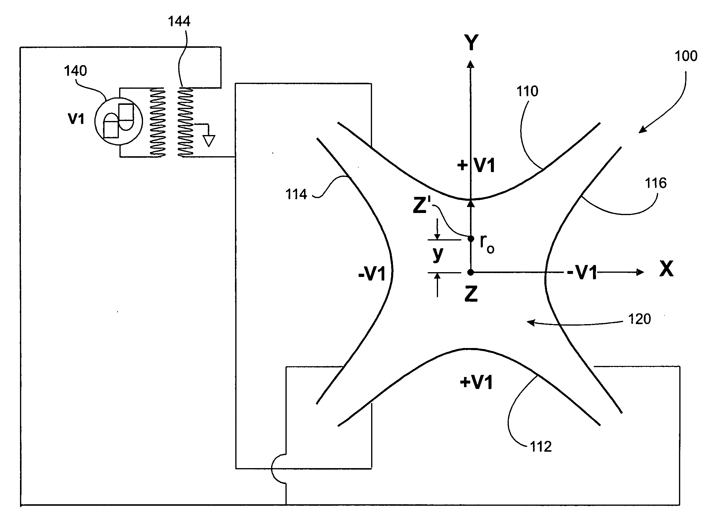
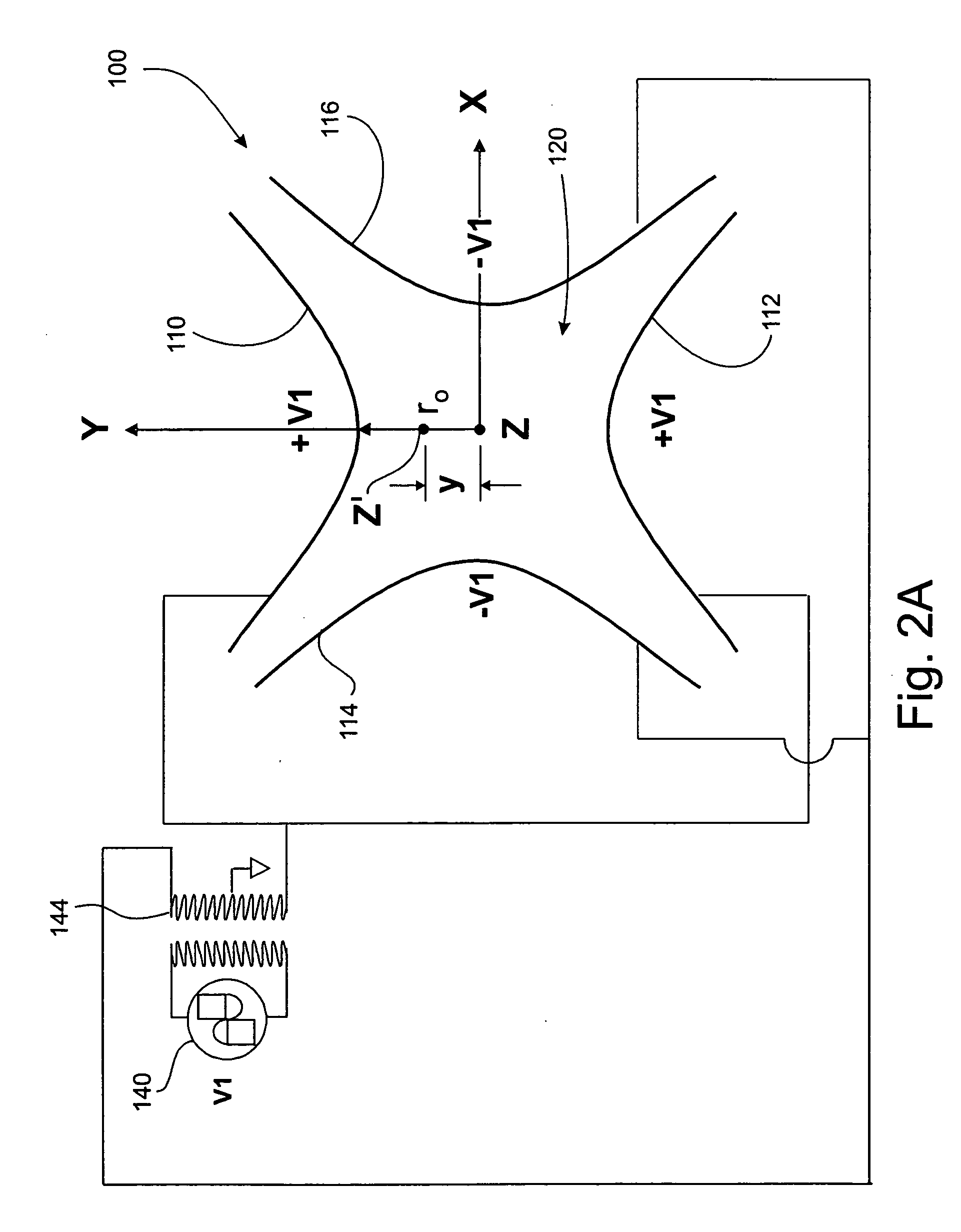
[0065] The subject matter disclosed herein generally relates to a linear ion trap apparatus and method that can be utilized in a wide variety of applications for which control over ion motion is desired. The apparatus and method are particularly useful for implementing the selection or sorting of ions according to their respective m / z ratios. Thus, the apparatus and method are particularly useful in mass spectrometry although are not limited to...


PUM


Abstract

A linear ion trap includes four electrodes and operates with an asymmetrical trapping field in which the center of the trapping field is displaced from a geometrical center of the trap structure. The asymmetrical trapping field can include a main AC potential providing a quadrupole component and an additional AC potential. The main AC potential is applied between opposing pairs of electrodes and the additional AC potential is applied across one pair of electrodes. The additional AC potential can add a dipole component for rendering the trapping field asymmetrical. The additional AC potential can also add a hexapole component used for nonlinear resonance. A supplementary AC potential can be applied across the same pair of electrodes as the additional AC potential to enhance resonant excitation. The operating point for ejection can be set such that a pure resonance condition can be used to increase the amplitude of ion oscillation preferentially in one direction. Ions trapped in the composite field can be mass-selectively ejected in a single direction to an aperture in one of the electrodes.

Description

FIELD OF THE INVENTION [0001] The present invention relates generally to a linear ion trap apparatus and methods for its operation. More particularly, the present invention relates to a linear ion trap apparatus and method for providing an asymmetrical electrical field for trapping ions, in which the center of the trapping field is displaced from the geometric center of the apparatus. BACKGROUND OF THE INVENTION [0002] Ion traps have been employed for a number of different applications in which control over the motions of ions is desired. In particular, ion traps have been utilized as mass analyzers or sorters in mass spectrometry (MS) systems. The ion trap of an ion trap-based mass analyzer may be formed by electric and / or magnetic fields. The present disclosure is primarily directed to ion traps formed solely by electric fields without magnetic fields. [0003] Insofar as the present disclosure is concerned, MS systems are generally known and need not be described in detail. Briefly...

Claims


Application Information

Patent Timeline
IPC IPC(8): H01J49/42
CPCH01J49/423
Inventor WELLS, GREGORY J.
Owner AGILENT TECH INC
Learn More