Magnetization pattern of rotor magnet for stepping motor

a technology of stepping motor and magnetization pattern, which is applied in the direction of rotating magnets, synchronous machines with stationary armatures, electrical apparatus, etc., can solve the problems of increasing torque ripple and a rotating speed ripple of the motor, non-magnetization drastically lowering the driving torque during driving, and the stepping motor is not suitable for the practical application, etc., to reduce the detent torque, reduce vibration and noise, and small drop of the driving torqu

a technology of stepping motor and magnetization pattern, which is applied in the direction of rotating magnets, synchronous machines with stationary armatures, electrical apparatus, etc., can solve the problems of increasing torque ripple and a rotating speed ripple of the motor, non-magnetization drastically lowering the driving torque during driving, and the stepping motor is not suitable for the practical application, etc., to reduce the detent torque, reduce vibration and noise, and small drop of the driving torqu

US20050264120A1Inactive Publication Date: 2005-12-01MITSUMI ELECTRIC CO LTD

Image

  • Magnetization pattern of rotor magnet for stepping motor
  • Magnetization pattern of rotor magnet for stepping motor
  • Magnetization pattern of rotor magnet for stepping motor

Examples


Embodiment Construction

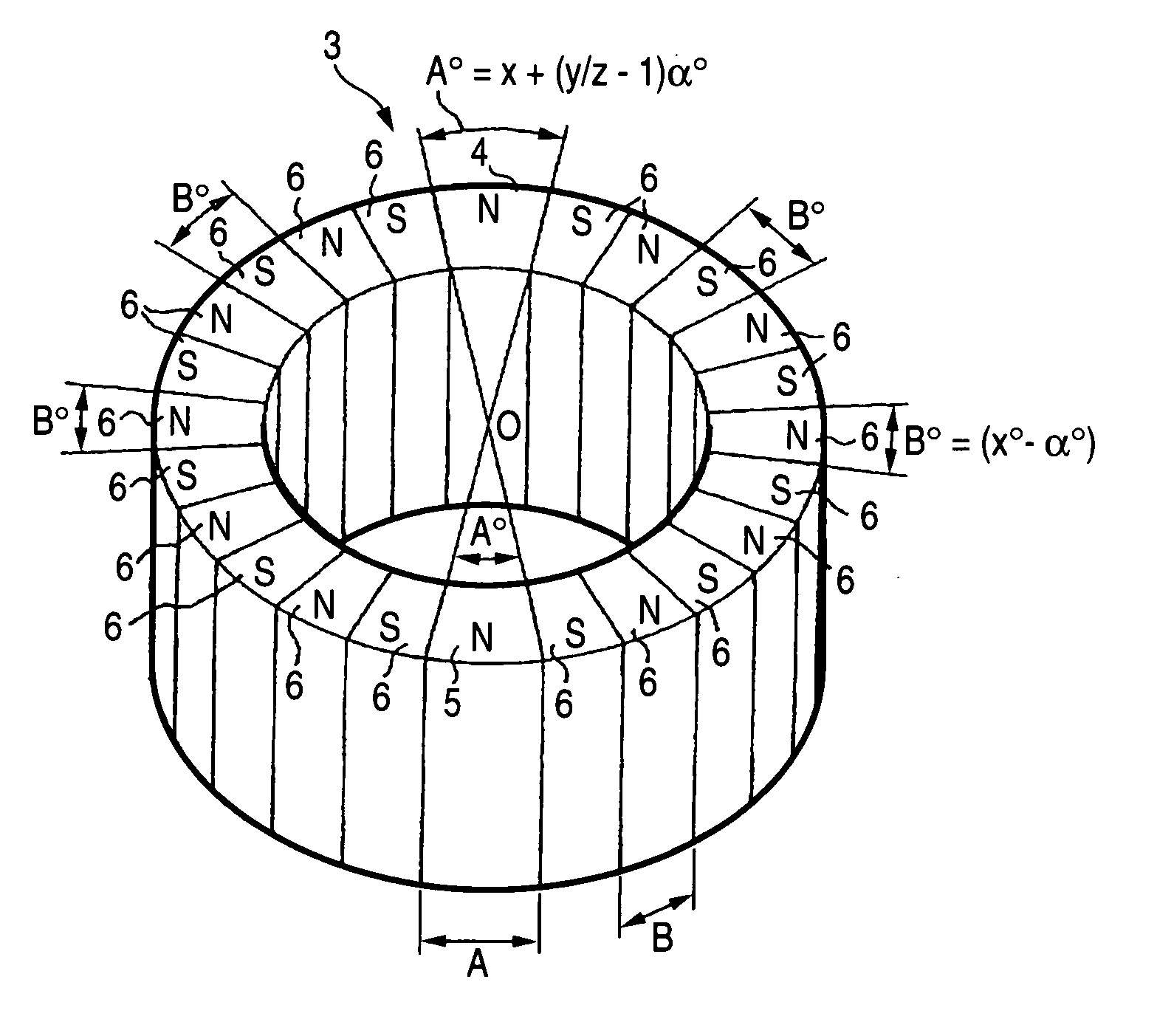
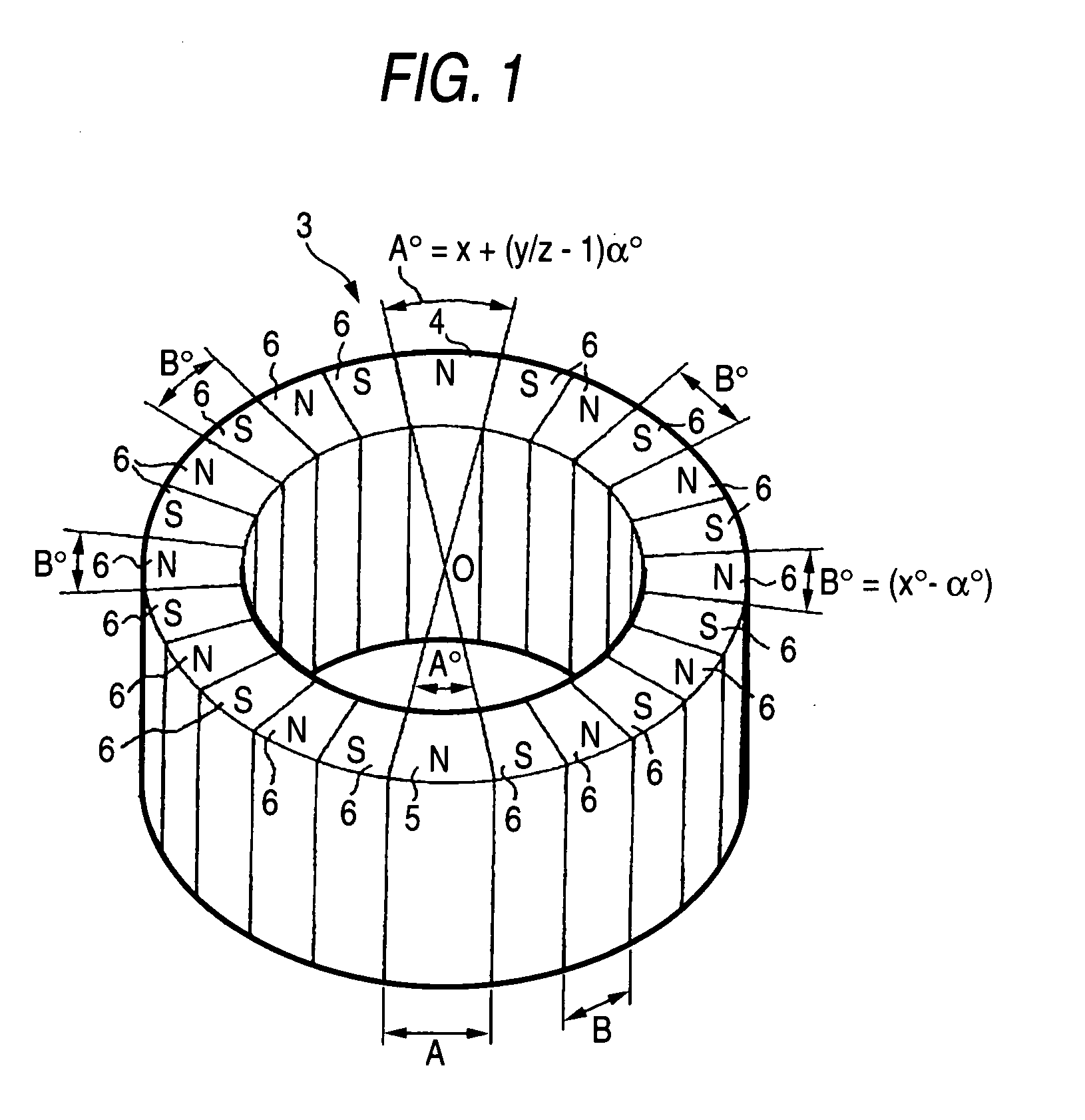
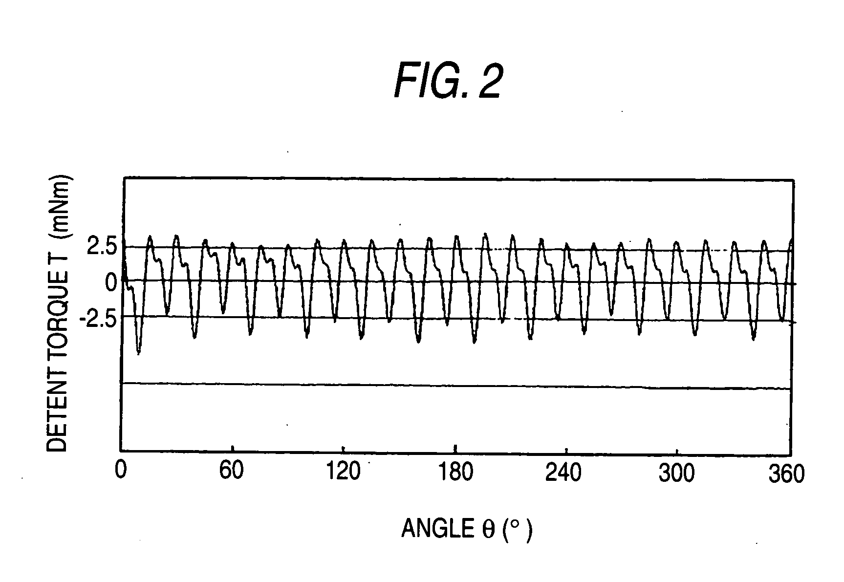
[0031] The invention accomplishes the objects of reducing the detent torque and suppressing the occurrence of vibration and noise by selecting the magnetization width A of the magnetization portions of the rotor magnet opposing each other with the rotary shaft of the rotor magnet as the center and the magnetization width B of the magnetization portions magnetized into the equal width at a plurality of other portions among the magnetization portions of the magnetic poles in the rotating direction of the rotor magnet so that they satisfy the relation A>B.

[0032] An embodiment of the invention will be hereinafter explained with reference to FIGS. 1 and 2. In the drawings, reference numeral 3 denotes a cylindrical rotor magnet. The rotor magnet 3 is arranged rotatably inside a stator unit (not shown in the drawings) having stator magnetic poles. A core part of the rotor magnet 3 is integrally fixed to a rotary shaft disposed at the center of rotation. The rotor unit described above seri...


PUM


Abstract

A magnetization pattern of a rotor magnet for a stepping motor includes a plurality of magnetization portions, which is provided on the rotor magnet in a rotation direction of the rotor magnet. The magnetization portions have different magnetic poles which are alternately arranged. Some magnetization portions of the magnetization portions have respectively magnetization widths A. Said some magnetization portions are opposed each other with a rotary axis or the rotor magnet as a center among said some magnetization portions. The other magnetization portions of the magnetization portions have respectively uniform widths B. Each of the magnetization widths A is greater than that of the uniform widths B.

Description

BACKGROUND OF THE INVENTION [0001] This invention relates to a magnetization pattern of a stepping motor. More particularly, the invention relates to a magnetization pattern of a stepping motor for reducing vibration and noise that occur during driving of the motor by changing a magnetization balance of Magnetic poles in a rotating direction or a rotor magnet. [0002] The stepping motor of this kind has been used appropriately in the past as an intermittent driving source of various kinds of appliances such as a printer, a facsimile, a disk drive, and so forth. In the stepping motor, a rotor is arranged rotatably inside a stator having a pole tooth, and the rotor has at its outer peripheral portion a cylindrical rotor magnet formed of a permanent magnet. When the stepping motor serially switches the supply of power to excitation coils of the stator magnetic poles, the rotor Is rotated and driven relative to the stator. [0003] In the rotor magnet 1, N poles and S poles are alternately...

Claims


Application Information

Patent Timeline
01 Dec 2005
Publication
US20050264120A1
IPC
H02K37/00; H02K37/14
CPC
H02K37/14
Inventors
HIRUMA, SHUICHI; SAKAMOTO, TAKANORI