
Actively tunable planar antenna

a planar antenna and active tunable technology, applied in the direction of antennas, antenna details, electrically short antennas, etc., can solve the problems of small antenna structures with a wide bandwidth on several frequency bands that are difficult to implement, type of antennas, and can only operate on one or two frequency bands properly, so as to achieve equal or even more efficiency and low height

Inactive Publication Date: 2005-12-01
NOKIA CORP
View PDF10 Cites 116 Cited by
  • Summary
  • Abstract
  • Description
  • Claims
  • Application Information

AI Technical Summary

Benefits of technology

[0008] The object of this invention is to provide a small antenna structure to be used for example in mobile terminals. The antenna of the invention can be actively tuned to operate on different frequency bands

Problems solved by technology

Especially small antenna structures with a wide bandwidth on several frequency bands is difficult to implement.
However, this type of antenna described in the EP 1 202 386 can only operate properly on one or two frequency bands.
Its operation is however limited to only one frequency band.
There have been some attempts to actively tune the antenna to different frequency bands, but these configurations have been difficult to implement, especially on the lower frequencies.
Also the bandwidth at the actively tuned frequency has been narrow, and the radiation efficiency low.

Method used


Image

  • Actively tunable planar antenna
  • Actively tunable planar antenna
  • Actively tunable planar antenna

Examples


Embodiment Construction

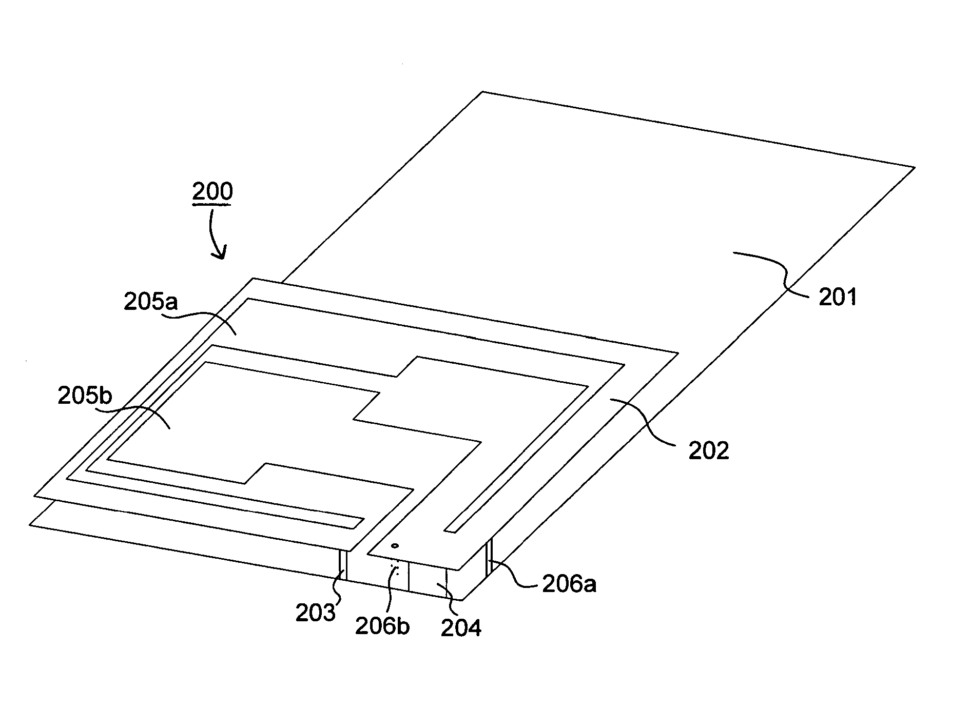
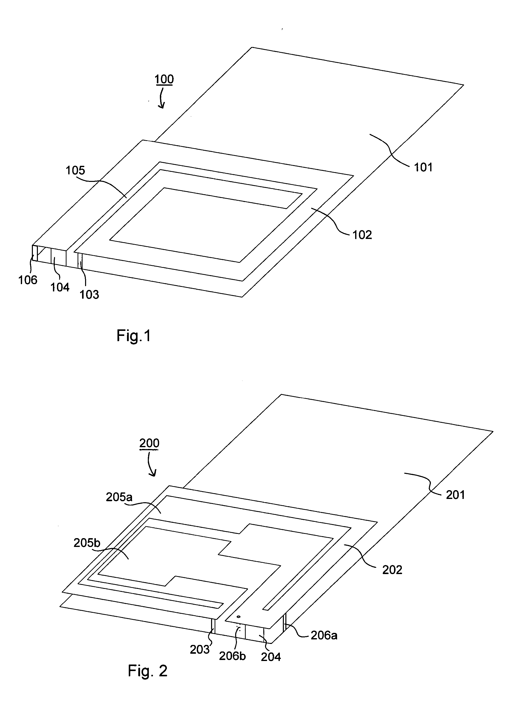
[0018] The radiating part of the antenna element according to an embodiment of the invention consists of one or two branches of a planar radiator starting at a feed point and ending to a grounding point forming a loop similarly as in the prior art antenna elements. The electrical length of the branches of the radiator is half wavelength. If the planar radiator consist of two branches, both branches can have their own grounding points, or they can have common grounding point if the ends of the branches are located close each other. There are also extra grounding points which are added to antenna element, these extra grounding points being located at a location between the feed point and the normal grounding point.

[0019] Normally the planar radiator consist of only one branch if the antenna element is to be used on only one frequency band, for example on the frequencies near 900 MHz or on the frequencies near 1800 MHz. If the antenna element is to be used on both lower and higher fre...


PUM


Abstract

This invention relates to an actively tunable patch antenna comprising a ground plane, a planar radiator, a feed point, a grounding line and first and second antenna branches separated from each other by a groove, the patch antenna further comprising one or more additional grounding points between the planar radiator and the ground plane. The invention further relates to a mobile terminal utilizing the tunable patch antenna of the invention.

Description

FIELD OF THE INVENTION [0001] The present invention relates to actively tunable patch antennas. The invention relates more specifically to actively tunable patch antennas used internally in mobile terminals. BACKGROUND OF THE INVENTION [0002] Demand for smaller mobile terminals is growing all the time. At the same time there is a need for the mobile terminal to be able to operate on several continents and on several frequency bands (for example GSM 900, GSM 1800 and GSM 1900). And in the future, when new mobile terminals with new technologies are implemented, the mobile terminal should be able to operate on the frequency bands of these technologies also (for example WCDMA 2000 or US GSM 850). [0003] The diminishing size of the mobile terminal and the requirement to be able to operate on several frequency bands sets requirements for the design of the mobile terminal. Especially small antenna structures with a wide bandwidth on several frequency bands is difficult to implement. [0004]...

Claims


Application Information

Patent Timeline
IPC IPC(8): H01Q1/24H01Q9/04
CPCH01Q9/0442H01Q1/243
Inventor TALVITIE, OLLIPANKINAHO, IIKKA
Owner NOKIA CORP
Learn More