Method and apparatus for transferring data within viewable portion of video signal

Inactive Publication Date: 2005-12-01
OPTINETIX ISRAEL
View PDF16 Cites 63 Cited by
  • Summary
  • Abstract
  • Description
  • Claims
  • Application Information

AI Technical Summary

Benefits of technology

[0006] It is a general object of the present invention to overcome the above disadvantages and to enable high enough bandwidth, and minimal noise for transmitting of commercial coupons and the like to the handheld devices. It is further an object to provide the data in a man

Problems solved by technology

Furthermore the user may not necessarily keep the device pointed in the right direction for the entir

Method used


Image

  • Method and apparatus for transferring data within viewable portion of video signal
  • Method and apparatus for transferring data within viewable portion of video signal
  • Method and apparatus for transferring data within viewable portion of video signal

Examples


Embodiment Construction

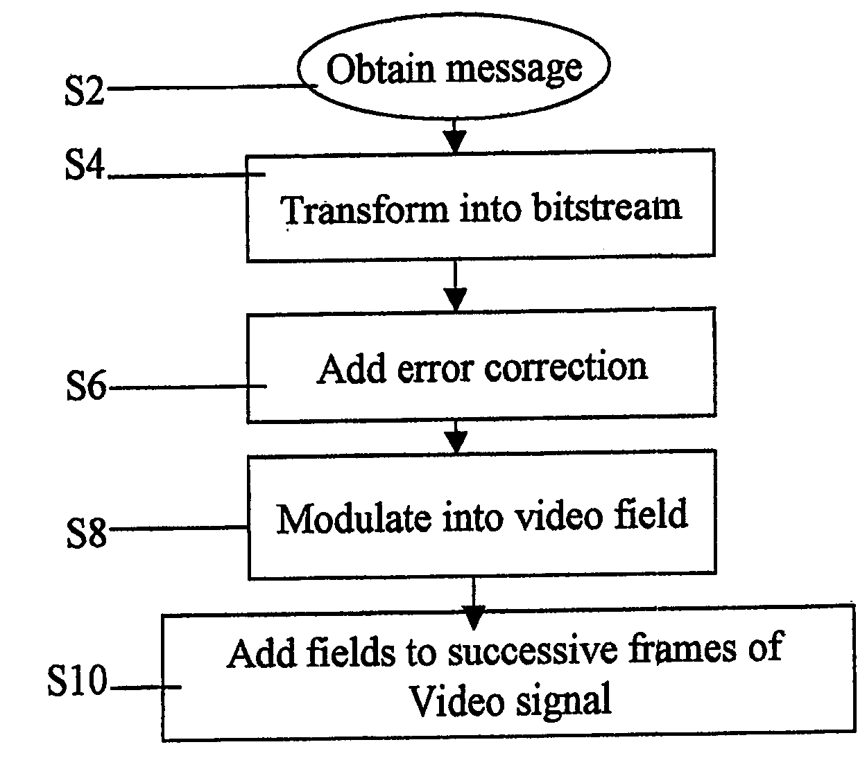
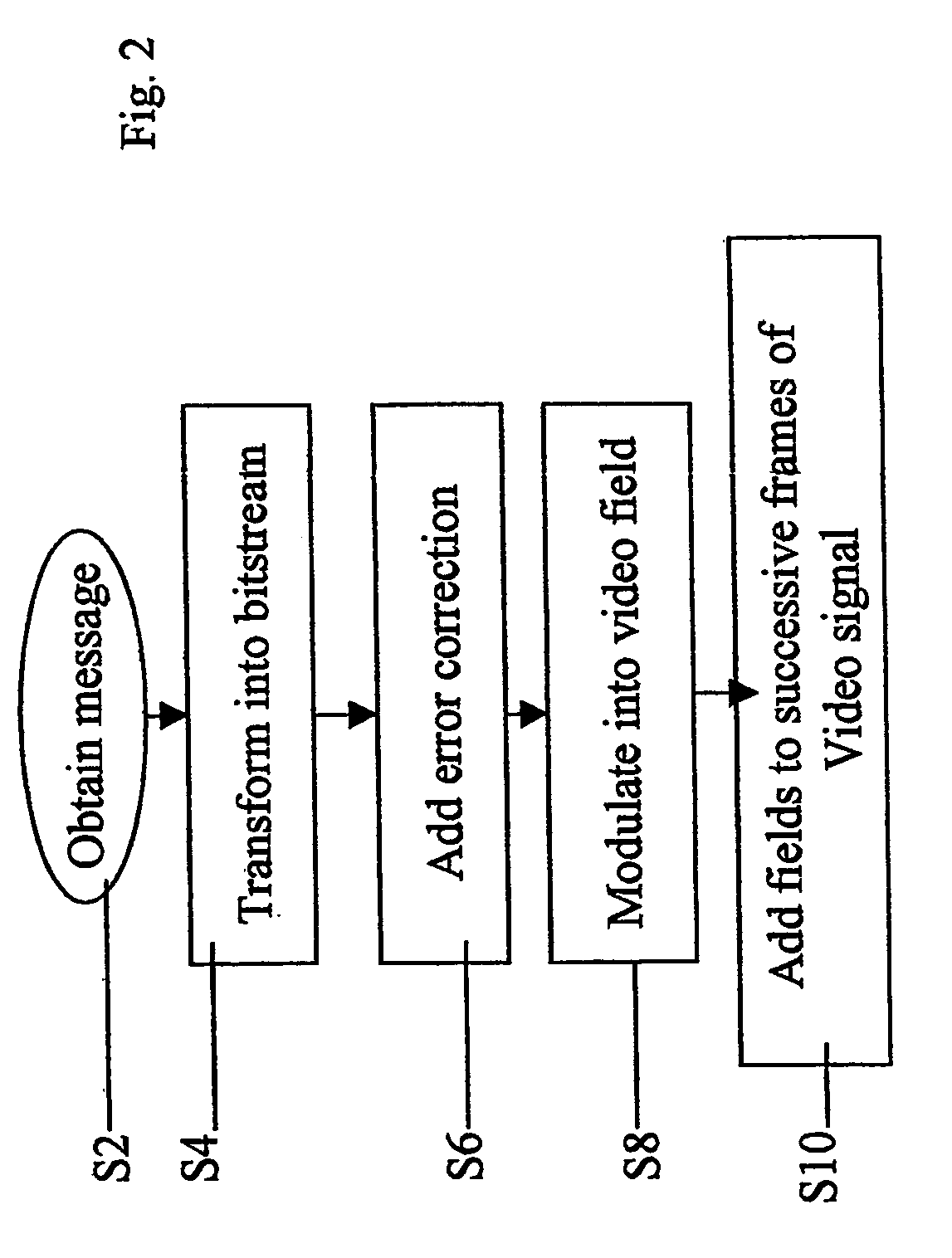
[0096] The present embodiments show a method and apparatus for encoding and decoding data within the visual field of a video signal, in a manner which is more robust to use conditions and provides better signal to noise ratio than the current art.

[0097] Before explaining at least one embodiment of the invention in detail, it is to be understood that the invention is not limited in its application to the details of construction and the arrangement of the components set forth in the following description or illustrated in the drawings. The invention is capable of other embodiments or of being practiced or carried out in various ways. Also, it is to be understood that the phraseology and terminology employed herein is for the purpose of description and should not be regarded as limiting.

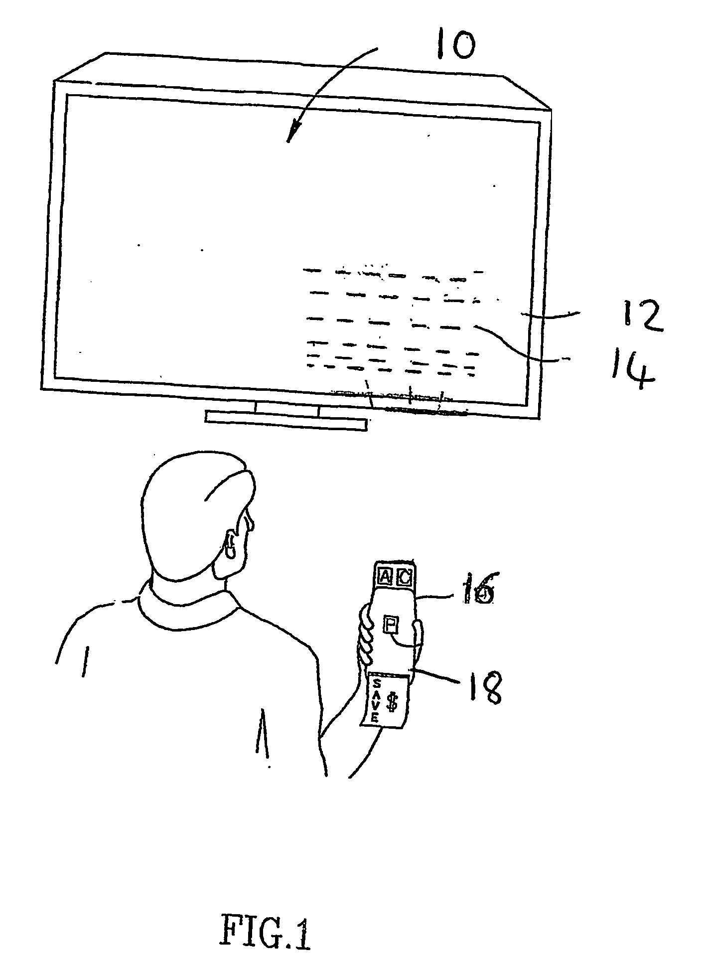
[0098] Referring now to the drawings, FIG. 1 illustrates data encoded in a video signal and an optical detection device according to a first preferred embodiment of the present invention. A television...


PUM


Abstract

A video signal has a visual image (12) and carries data for optical detection (54) via the image. The data for optical detection is encoded (52) as data bits in a plurality of lines within a defined region (14) within the image. A corresponding decoder (16, 58) uses maximal energy methods to detect the defined region prior to decoding the data.

Description

FIELD AND BACKGROUND OF THE INVENTION [0001] The present invention relates to a method and apparatus for transferring data over the viewable portion of a video signal, and more particularly but not exclusively to a method and apparatus that provides electronically downloadable data obtainable by optical means from a video screen. [0002] The most common approach to applying data to a video signal currently in use is to insert data during the vertical blanking interval, such as in the generation of closed captioning signals. A major disadvantage of this method is that data in the vertical blanking interval can be removed or changed by the TV broadcaster, usually quite unintentionally, as part of the incidental operation of the broadcasting infrastructure. In certain cases the same program may be broadcast simultaneously in analog and digital formats, the data being preserved in the analog format but lost say in the digital format. Placing the data within the visual signal overcomes th...

Claims


Application Information

Patent Timeline
IPC IPC(8): G06Q30/00H04H1/00H04H20/30H04H20/31H04H60/25H04H60/48H04N7/025H04N7/08H04N7/087
CPCG06Q30/02H04H20/16H04H20/30H04N7/08H04H60/25H04H60/48H04N7/025H04H20/31
Inventor ILAN, GABRIELPERSKI, HAIM
Owner OPTINETIX ISRAEL
Why Eureka
Try Eureka