Agile beam steering mirror for active raster scan error correction

a technology of raster scan and steering mirror, applied in the field of raster output scanner, can solve the problems of serious deformation of print quality, bow errors less than 10 microns, and errors in the quality of the scan line on the photoreceptor, and achieve the effect of eliminating higher-cost optical compensating elements and high bandwidth

Active Publication Date: 2009-06-25
XEROX CORP
View PDF11 Cites 2 Cited by
  • Summary
  • Abstract
  • Description
  • Claims
  • Application Information

AI Technical Summary

Benefits of technology

[0016]Accordingly, the present invention is directed to a system and method for providing a low-cost micromachined piezoelectric steering element that has high enough bandwidth to actively correct for scan line spacing error, in-line skew and bow, and color registration. It can replace a standard folding mirror in existing ROS designs and may eliminate higher cost optical compensating elements.
[0017]In order to correct for scan line spacing error, in-line skew and bow, and color registration, an agile beam steering system is provided that can dynamically change line position in real time (i.e., while the raster beam is scanning). In addition to having a high resonant frequency, the agile beam steering system of the present invention has low mechanical Q such that vibrations do not excite ringing. Finally, the agile beam steering system of the present invention may be implemented at relatively low cost and complexity and in a small footprint, thus providing an overall commercially reasonable solution.
[0018]According to one aspect of the invention, an agile mirror device is introduced into the optical path of a ROS system. The agile mirror is composed of a micromachined silicon mirror mounted at the end of a cantilevered piezoelectric bimorph bending actuator. This bender is in turn anchored to a low expansion ceramic substrate on which two drive electrodes and a sensing capacitive electrode are formed. The miniature mirror is attached to the end of the piezoelectric bender along one central ridge or several posts situated along the midpoint of the mirror width. These attachment points serve to isolate mounting stresses due to epoxy attachment as well as small differences in the coefficient of expansion (CTE) between the piezoelectric bender and the silicon mirror.
[0019]A capacitive air gap is provided between the bimorph bender and the sensing electrode to form a sensing capacitive structure. This air gap provides sense capacitance as well as air damping of the structure in order to reduce or eliminate ringing.

Problems solved by technology

Unfortunately, unavoidable imprecision in the shape and / or mounting of these optical elements inevitably introduces anomalies in the quality of the scan line on the photoreceptor.
However, in color printing, particularly when using multiple raster output scanners, such errors seriously degrade print quality.
Indeed, when multiple raster output scanners are used, if one bow forms a frown while the other forms a smile, bow errors of less than 10 microns degrade the final image.
One source of these artifacts is a slight imperfection in the advancement of the photoreceptor relative to the scan line.
This gaps affects the tone of the printed image along an entire scan line.
However, this approach is often prohibitively expensive, particularly when machine assembly is taken into consideration.
Even then, meeting a 2 micron bow deviation requirement cannot always be met.
However, that approach requires the introduction of another piece of glass into the optical path.
Furthermore, in many raster output scanners it is the post-polygon optical system that introduces most of the scan line position error.
Consequently, printing speed is then limited by the resonant frequency of the feedback control system.
Furthermore, bow and skew can lead to color registration or banding issues on part of a scan line even when feedback control systems are use because such systems measure scan positions at the edges of the photoreceptive drum or belt.

Method used


Image

  • Agile beam steering mirror for active raster scan error correction
  • Agile beam steering mirror for active raster scan error correction
  • Agile beam steering mirror for active raster scan error correction

Examples


Embodiment Construction

[0044]Various embodiments of an agile mirror device for ROS systems according to the present invention will now be described, as well as example methods of manufacturing and components employed in the operation of same. It will be understood that the following are merely examples of various aspects of the present invention, and provide a framework for an understanding of the scope of the present invention.

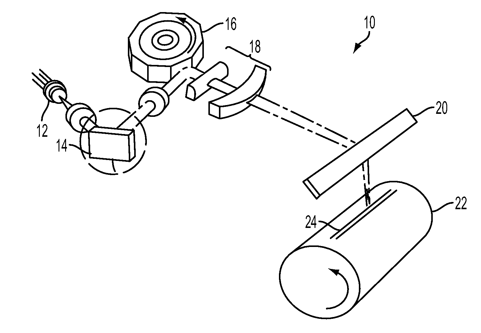
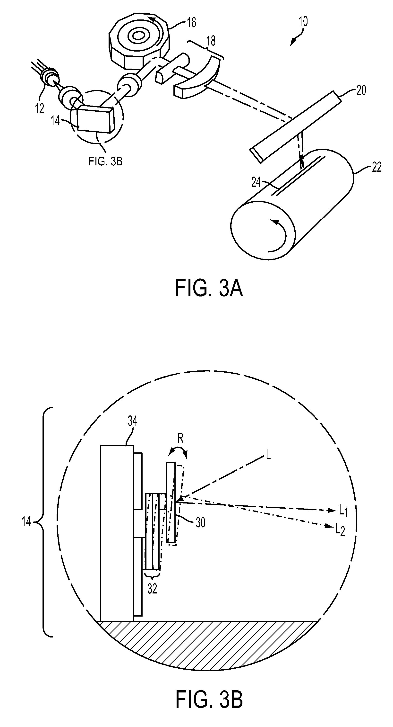
[0045]With this in mind, shown in FIG. 3A is a ROS system 10 which includes a light source such as laser 12, the agile beam steering mirror assembly 14 according to the present invention, a rotating polygon mirror assembly 16, scan optic assembly 18, mirror 20, and photoreceptive drum 22. Following the path of light emitted from laser 12, a light beam is incident on agile beam steering mirror assembly 14 which adjusts the beam position as described further below. The beam is directed by the agile mirror system 14 to the rotating polygon mirror 16, which causes the beam to move in t...


PUM


Abstract

Scan line position error resulting in banding, bow, skew, etc. is corrected by way of an agile beam steering mirror assembly in a ROS printing system and the like. The agile beam steering mirror system comprises a piezoelectric bending actuator fixedly mounted to a substrate at a proximate end thereof. A mirror structure is mounted at a free distal end of the bending actuator. Voltage applied to the bending actuator causes rotation of the mirror to thereby correct for positional errors of the scan line. Correction waveforms may be stored in control memory associated with the agile beam steering mirror assembly. A capacitive sensing circuit using a sensing electrode located beneath the free end of the bending actuator may be used in a feedback arrangement to determine and control mirror position.

Description

BACKGROUND OF THE INVENTION[0001]1. Field of the Invention[0002]This invention relates to raster output scanners (ROS). More particularly it relates to an active element in the optical path of a ROS which addresses scan line skew and bow correction.[0003]2. Description of the Prior Art[0004]Electrophotographic marking is a well-known, commonly used method of copying or printing documents. Electrophotographic marking is performed by exposing a charged photoreceptor with a light image representation of a desired document. The photoreceptor is discharged where exposed, creating an electrostatic latent image of the desired document on the photoreceptor's surface. Toner particles are then deposited onto that latent image, forming a toner image, which is then transferred onto a substrate, such as a sheet of paper. The transferred toner image is then fused to the substrate, usually using heat and / or pressure, thereby creating a permanent record of the original representation. The surface o...

Claims


Application Information

Patent Timeline
Patent Type & Authority Applications(United States)
IPC IPC(8): G02B26/00
CPCB41J2/471G02B26/124G02B26/105
Inventor STOWE, TIMOTHY D.
Owner XEROX CORP
Why Eureka
Try Eureka