
Optical information recording apparatus

a technology of optical information and recording equipment, applied in the field of optical information recording equipment, can solve problems such as poor precision, and achieve the effects of avoiding inappropriate environment, high precision, and effective use of the test recording area of the media

Inactive Publication Date: 2005-12-01
TAIYO YUDEN KK
View PDF6 Cites 17 Cited by
  • Summary
  • Abstract
  • Description
  • Claims
  • Application Information

AI Technical Summary

Benefits of technology

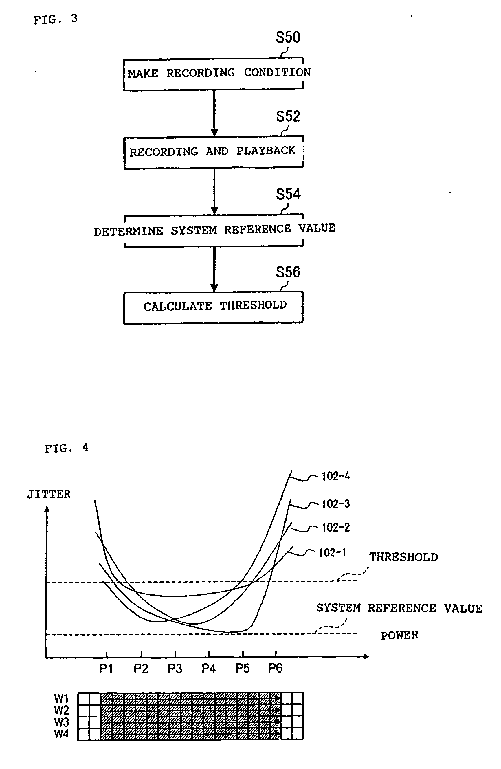
The present invention provides an optical information recording apparatus for recording information on optical recording media using pulse irradiation of laser light. The apparatus includes a means for obtaining a recording margin by comparing a reproduction characteristic with a preset standard, and inspecting the recording quality based on the size of the recording margin. The technique for inspecting the recording quality based on the recording margin is more precise than the technique for simply comparing the reproduction characteristic with the standard value. The recording margin can be determined based on the difference between power values or the difference between pulse width values. The apparatus can also inform the user of the recording quality with various techniques such as changing the drive's rotational speed, notifying the user through mechanical operation or auditory or visual techniques, or recording specific information into the media or selecting a suitable media for the drive. The recording condition can also be determined based on the result of the recording quality inspection. Overall, the present invention provides an effective inspection technique for recording quality control.

Problems solved by technology

As the index of the reproduction standard, an error rate in addition to the jitter may be used, and in addition, a characteristic index such as a β value or a modulation level may be used although it may give poor precision.

Method used


Image

  • Optical information recording apparatus
  • Optical information recording apparatus
  • Optical information recording apparatus

Examples


example 2

DISPLAY EXAMPLE 2

Displaying the Error Comment and so on the Monitor

[0276] The contents of warning to be shown to the user are indicated on the monitor. If the approval or the instruction from the user is required, a response from the user is awaited.

example 3

DISPLAY EXAMPLE 3

Opening the Drive Tray

[0277] The user is informed of a warning by ejecting the media. If the approval or the instruction from the user is required, an error comment and so on may be displayed on the monitor and a response from the user is waited.

example 4

DISPLAY EXAMPLE 4

Producing a Warning Sound

[0278] The user is informed of a warning by producing the warning sound. If the approval or the instruction from the user is required, an error comment and so on is displayed on the monitor and a response from the user is waited.


PUM

PropertyMeasurementUnit
thresholdaaaaaaaaaa
thresholdaaaaaaaaaa
poweraaaaaaaaaa

Abstract

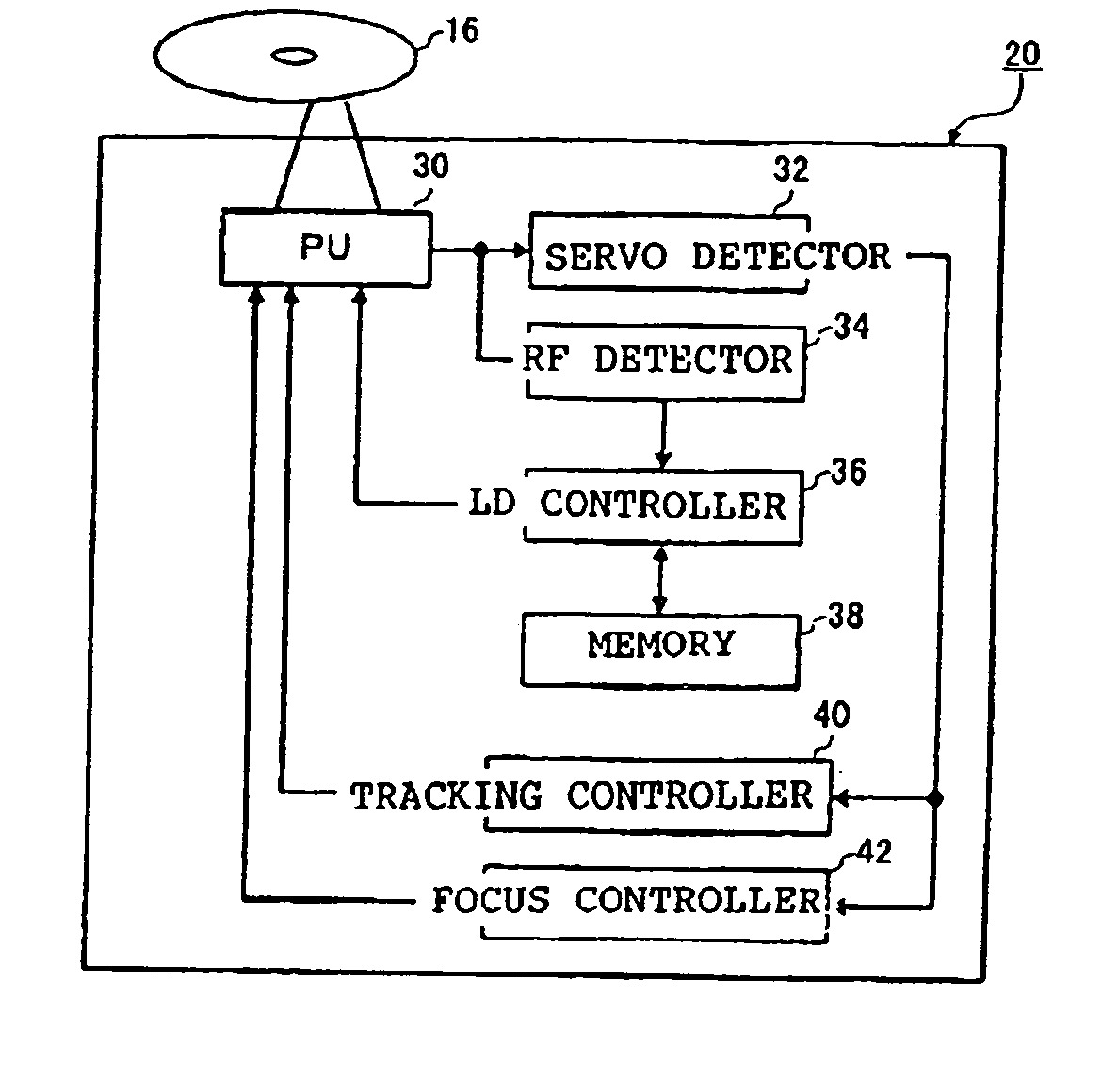
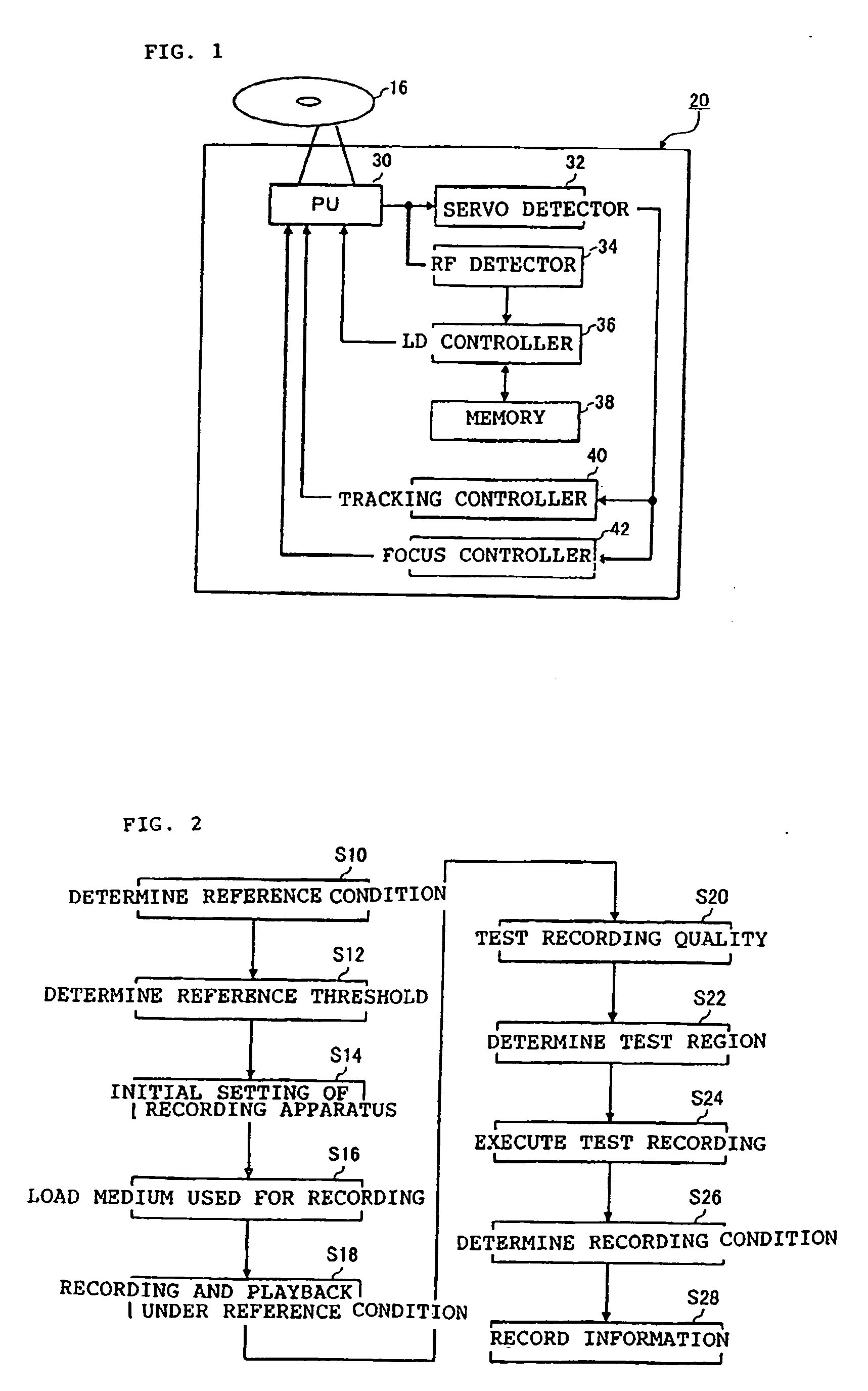
There is provided an effective inspection technique of recording quality decided by a combination of a drive and a media. A standard media as a quality standard for various media is recorded and reproduced for each drive, thresholds obtained by multiplying a characteristic value obtained as a result of the record reproduction by a preset factor are stored in a storage area within each drive. When a record of information in a record object media is performed, the record object media is recorded and reproduced using a plurality of recording conditions accompanied with change of a power or a pulse width, an approximation curve is obtained from a plurality of characteristic values obtained as a result of the record reproduction, and the recording quality inspection of the media is performed based on the amount of margin obtained according to a positional relationship between the approximation curve and the threshold.

Description

BACKGROUND OF THE INVENTION [0001] 1. Field of the Invention [0002] The present invention relates to optical information recording apparatuses such as optical disk recording apparatuses, and more particularly, to an optical information recording apparatus equipped with an effective inspection means for a recording quality. [0003] 2. Description of the Related Art [0004] For recording of an optical information recording media (hereinafter, referred to as media) represented by CD-R or DVD-R, compatibility between the media for record and a recording apparatus for record (hereinafter, referred to as a drive) depends on a combination thereof. Factors for this may include a media factor that the optimum recording condition is varied depending on a material of the media and un-uniformity of film formation upon manufacturing of the media and a drive factor that the optimum condition is varied depending on pickups or semiconductor lasers, which constitute the drive, or un-uniformity of asse...

Claims


Application Information

Patent Timeline
Patent Type & Authority Applications(United States)
IPC IPC(8): G11B5/09G11B7/0045G11B7/00G11B7/007G11B7/125G11B7/1267
CPCG11B7/00456G11B7/00458G11B19/041G11B7/1267G11B7/00736
Inventor KAKIMOTO, HIROYASEKIGUCHI, MITSUOMATSUDA, ISAOSATO, YOSHIKAZU
Owner TAIYO YUDEN KK
Learn More