Image-forming device

Active Publication Date: 2005-12-01
BROTHER KOGYO KK
View PDF1 Cites 3 Cited by
  • Summary
  • Abstract
  • Description
  • Claims
  • Application Information

AI Technical Summary

Benefits of technology

[0007] In view of the foregoing, it is an object of the present invention to provide an image-forming device controls the fixing

Problems solved by technology

However, the fixing heater sometimes happens to reach an excess high temperature due to any unexpected reasons.
However, such a software process is not as reliable since the software may happen to 0be o

Method used


Image

  • Image-forming device
  • Image-forming device
  • Image-forming device

Examples


Embodiment Construction

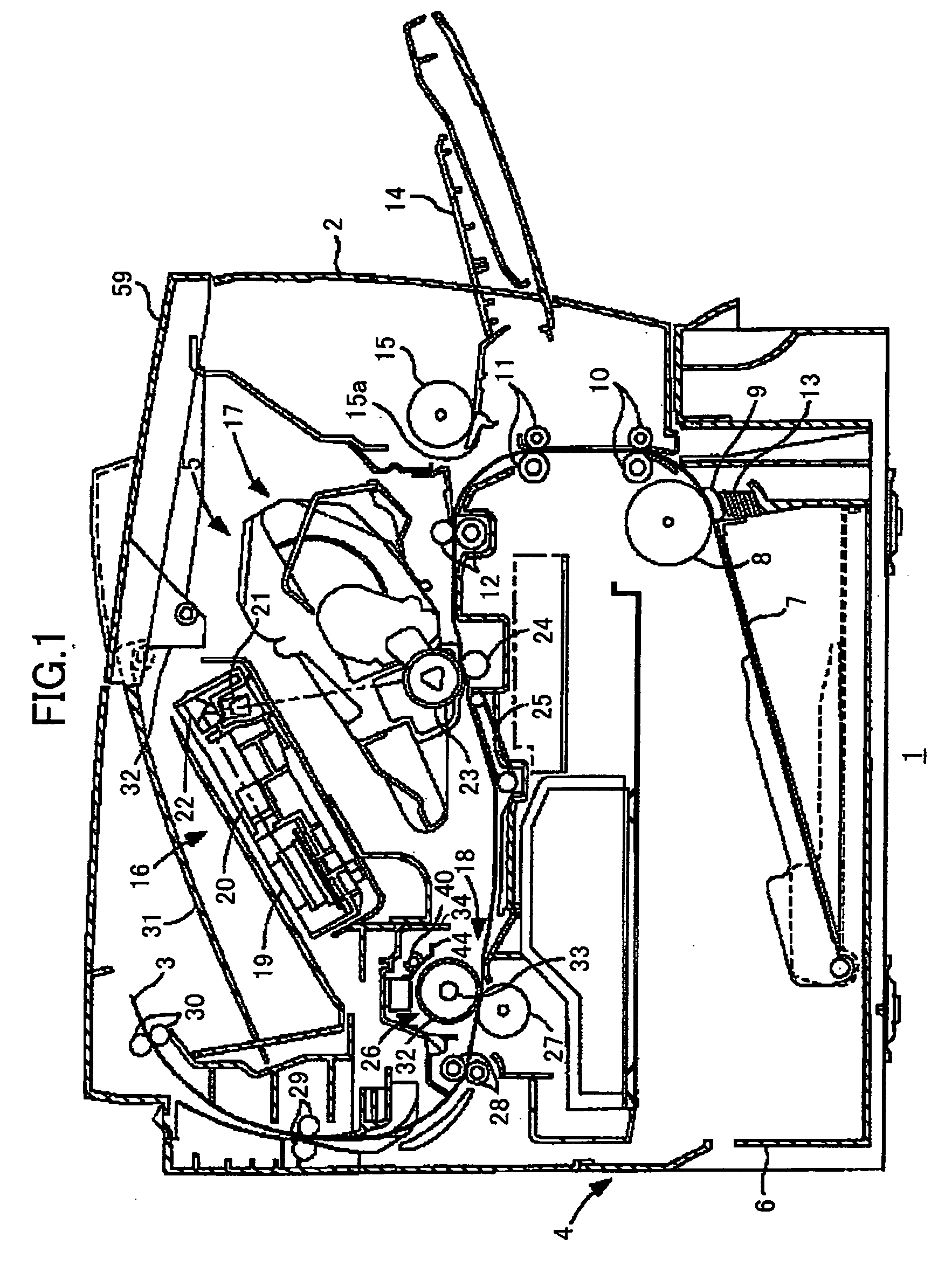
[0021] Next, an image-forming device according to a preferred embodiment of the present invention will be described with reference to the accompanying drawings. Referring to FIG. 1, a laser printer 1 includes a feeding unit 4 for feeding sheets 3 of paper, an image-forming unit 5 for forming images on the sheets 3 supplied from the feeding unit 4, and a controller 100 (not shown) for controlling the feeding unit 4 and image-forming unit 5, within a main casing 2. The image-forming unit 5 includes a scanning unit 16, a process cartridge 17, a transfer roller 24, and a heat fixing device 18.

[0022] The feeding unit 4 is disposed in the bottom section of the main casing 2 and includes a paper tray 6 detachably loaded in the feeding unit 4, a paper pressing plate 7 disposed in the paper tray 6, a feeding roller 8 and a separating pad 9 disposed above one end of the paper tray 6, a pair of conveying rollers 10 and a pair of conveying rollers 11 disposed downstream of the feeding roller 8...


PUM


Abstract

A laser printer capable of controlling the operation of a fixing heater to heat a roller, including an energizing circuit for energizing a heater, a temperature detecting circuit such as thermistors, a noise canceling circuit, and a control circuit for controlling the energizing circuit and the heater. After receiving a voltage indicating an abnormal temperature of the heater over a prescribed length of time duration, the noise canceling circuit is configured to transmit a LOW level voltage to a latch circuit as an abnormality signal. The control circuit suspends the energization of the heater in response to the abnormality signal.

Description

BACKGROUND OF THE INVENTION [0001] 1. Field of the Invention [0002] The present invention relates to an image-forming device, and particularly to a mechanism for controlling a fixing heater in the image-forming device. [0003] 2. Related Art [0004] An image-forming device generally includes a fixing unit for fixing a toner image to a recording medium after the image has been transferred thereon. The fixing unit is configured of a fixing roller including a fixing heater inside, and a pressure roller that contacts the fixing roller with pressure. The recording medium is pinched between and conveyed by the fixing roller and pressure roller with the surface of the recording medium with the toner image facing the fixing roller. The heat from the fixing roller melts and fixes the toner image to the recording medium. [0005] However, the fixing heater sometimes happens to reach an excess high temperature due to any unexpected reasons. Japanese patent application publication No. HEI 10-307514...

Claims


Application Information

Patent Timeline
IPC IPC(8): G03G15/20
CPCG03G15/2039G03G15/55
Inventor KUBO, ISAO
Owner BROTHER KOGYO KK
Why Eureka
Try Eureka