Flexible rail multiaxis machine tool and method

a multi-axis, machine tool technology, applied in the direction of manufacturing tools, metal working devices, drilling/boring measurement devices, etc., can solve the problems of not being developed or the placement of holes in the structure is generally limited to human speeds, and the apparatus is not developed or shown to be economically feasible for general use. , to achieve the effect of convenient mounting and detachment from the workpi

Active Publication Date: 2005-12-01
THE BOEING CO
View PDF23 Cites 55 Cited by
  • Summary
  • Abstract
  • Description
  • Claims
  • Application Information

AI Technical Summary

Benefits of technology

[0008] The foregoing needs are met, to a great extent, by the present invention, wherein, in one embodiment, a flexible rail machine tool method and apparatus is provided that is able to conform to a workpiece surface that has significant curvature and is able to perform machining operations such as drilling holes within a work zone on the workpiece. In another aspect, the flexible rail machine tool method and apparatus is further able to traverse a surface along at lease one axis without manual repositioning and is able to perform machining operations such

Problems solved by technology

Placement of holes in the structure has thus generally been limited to human speeds, and has required extensive inspection.
Such apparatus, however, has not been developed or shown to be economically feasible for general use.
Further, installation and removal of the rail may easily mar the workpiece.
Also, alignment is critical and may be time-consuming.
As well, only a small percentage of needed holes are likely to fall on any one line, so devising the drilling patterns, preparing mounting holes, and repeatedly repositioning the rail can be tedious.
I

Method used


Image

  • Flexible rail multiaxis machine tool and method
  • Flexible rail multiaxis machine tool and method
  • Flexible rail multiaxis machine tool and method

Examples


Embodiment Construction

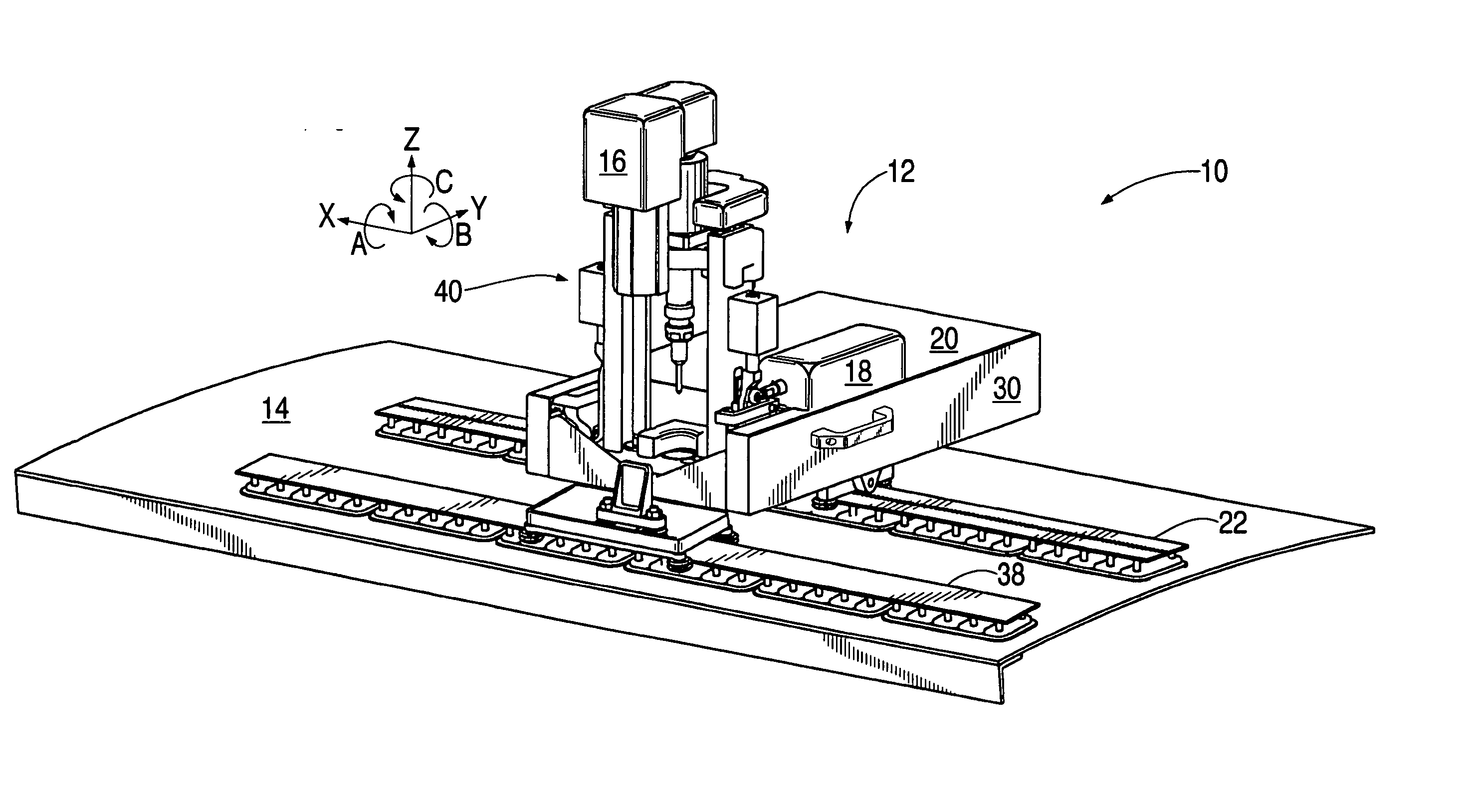
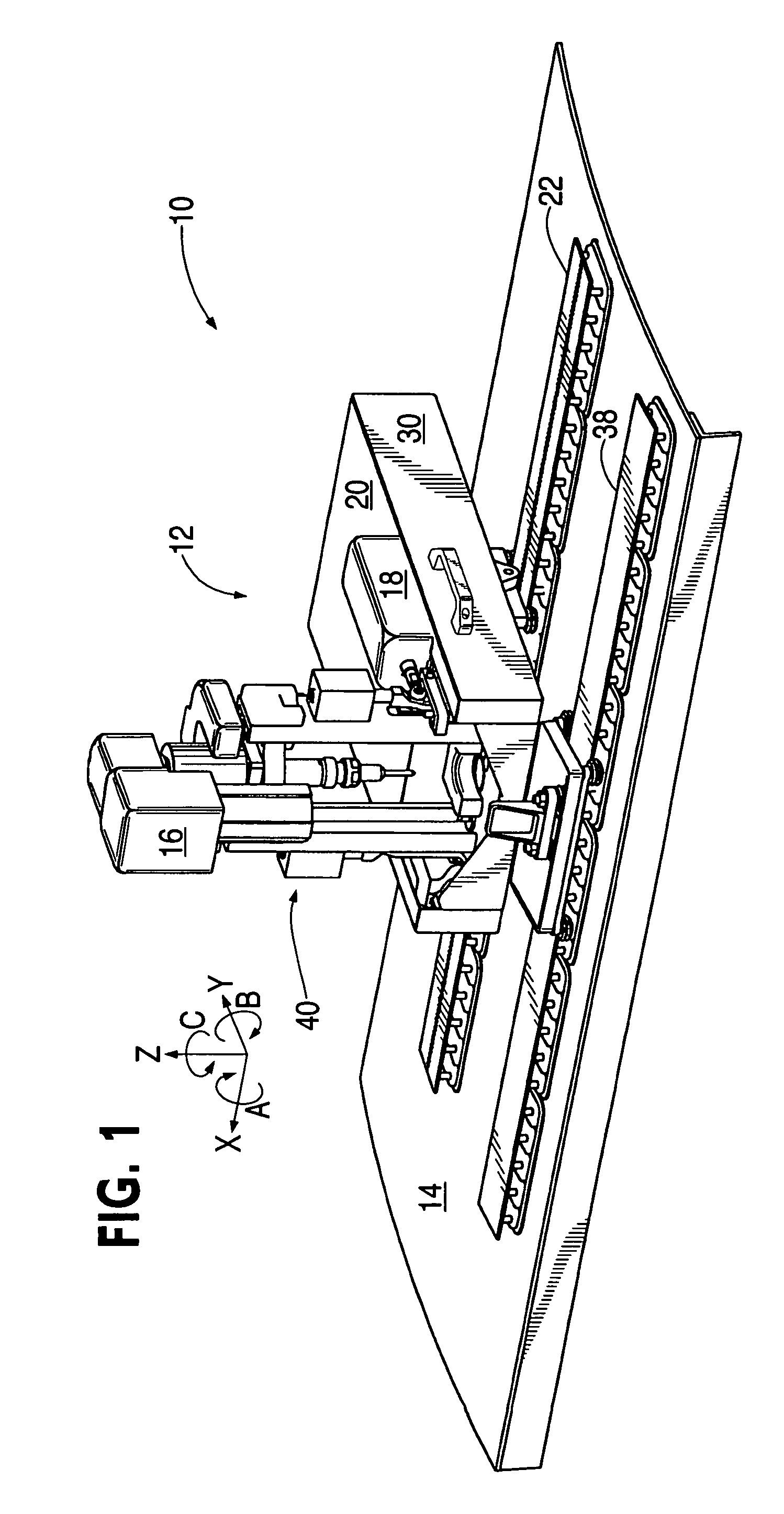
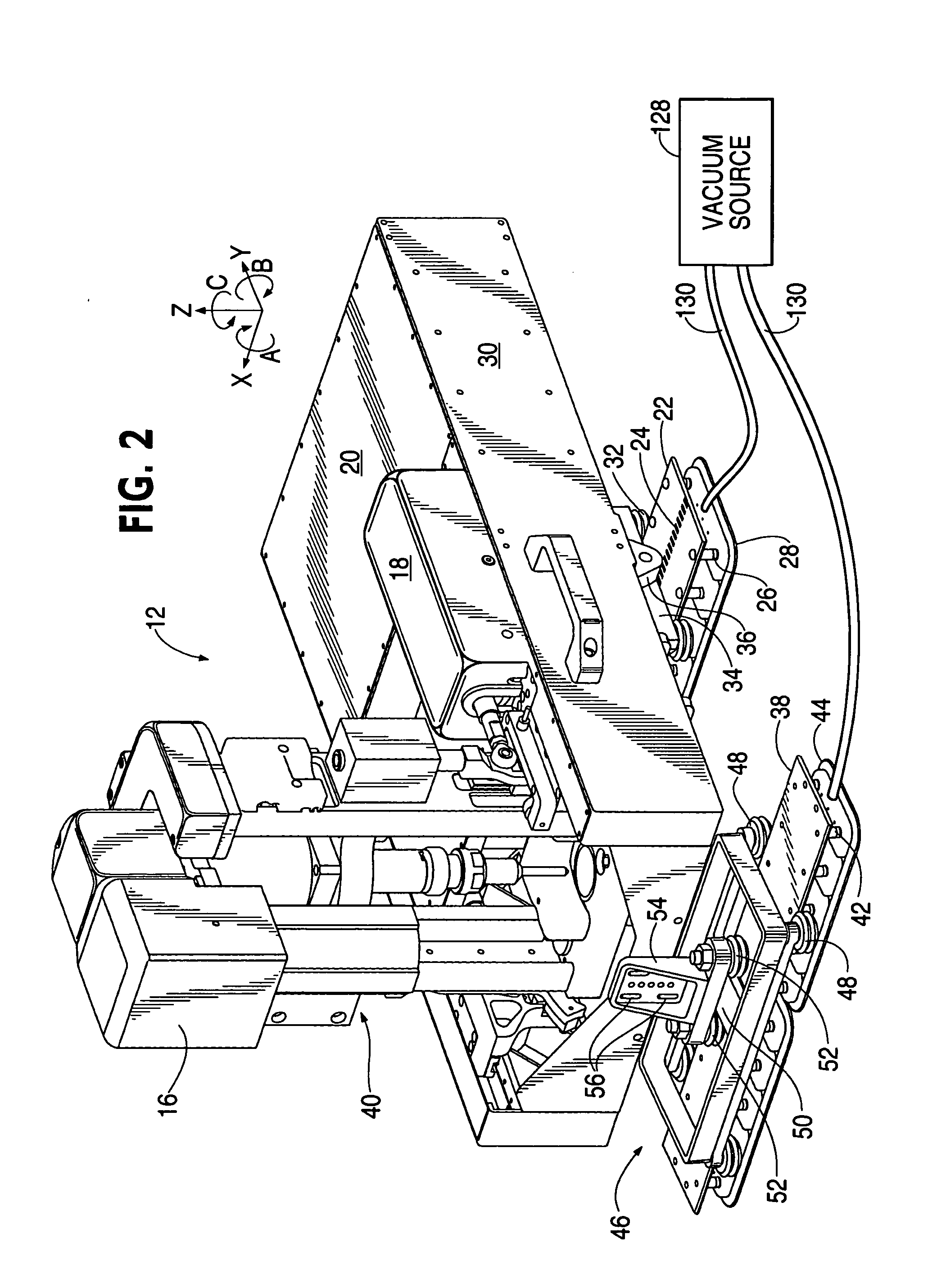
[0023] An embodiment in accordance with the present invention provides a rail system for positioning a toolhead above a workpiece that may have significant curvature in one or more axes. Smooth motion of the toolhead on a rail suspension system is achieved in the exemplary embodiment through use of a main rail system comprising one or more relatively long and wide, flat, flexible rails with vee-shaped rail edge faces contacted by mating bearing devices, such as rollers, on the toolhead. Motorized drive of the toolhead along a rail system axis parallel to the rail edge faces—hereinafter the longitudinal axis—in the exemplary embodiment is achieved using a pinion gear on the toolhead and a rack formed into the primary rail.

[0024] The toolhead may be capable of self-driven motion along and about multiple axes. In addition to having rollers and a motor drive to permit traversing the longitudinal extent of the main rails, the toolhead may be equipped with cross rails, which may preferab...


PUM

PropertyMeasurementUnit
Forceaaaaaaaaaa
Pressureaaaaaaaaaa
Poweraaaaaaaaaa

Abstract

A flexible rail machine tool couples temporarily to a structure by vacuum cups and positions a tool head at any desired point over an area. The toolhead can perform operations such as drilling, bolt insertion, and acquisition of dimension data. The flexible rail can conform to surface curvature in one or more axes. Tool head perpendicularity to the structure can be sensed and adjusted as needed. The as-attached position of the rail may be compensated for through coordinate transformation, allowing holes, for example, to be placed with substantial precision.

Description

FIELD OF THE INVENTION [0001] The present invention relates generally to manufacturing tools and automation. More particularly, the present invention relates to rail-mounted machine tools and automated positioning systems. BACKGROUND OF THE INVENTION [0002] Classic aircraft production has, since early in the history of hard-skinned aerostructures, involved making templates and aligning them on fuselage and flight surface skins, then drilling through holes in the templates using hand-held drills to prepare the aerostructure for installation of rivets and screws. Placement of holes in the structure has thus generally been limited to human speeds, and has required extensive inspection. [0003] In theory, a massive robotic apparatus could be developed that could autonomously place holes at any location on a workpiece such as an aerostructure, with the robotic apparatus placed, for example, on a monument base separated from the workpiece, and with each hole drilled with accuracy limited b...

Claims


Application Information

Patent Timeline
IPC IPC(8): B23Q9/00
CPCB23Q9/0014B23Q2210/008Y10T409/306384Y10T29/51Y10T408/56253Y10T408/554B23Q9/00
Inventor BOYL-DAVIS, THEODORE M.BUTTRICK, JAMES N. JR.GAGE, ROGER A.JONES, DARRELL D.BANKS, DAVID P.OUTOUS, RONALD WAYNEARNTSON, PAUL REUBENMURPHY, JAMES C.MERKLEY, ALAN R.
Owner THE BOEING CO
Why Eureka
Try Eureka