Image replication element and method and system for producing the same

Inactive Publication Date: 2005-12-20
DAY INT
View PDF24 Cites 10 Cited by
  • Summary
  • Abstract
  • Description
  • Claims
  • Application Information

AI Technical Summary

Benefits of technology

[0005]Accordingly, there is a desire in the industry to directly record information on a photosensitive layer using digital information without a mask. With digital information, digitized images may be transmitted from a distant location, and corrections can be made easily and quickly by adjusting the digitized image. In addition, the digitized image could be either positive or negative, eliminating the need to have both positive-working and negative-working photosensitive materials, or positive and negative masks, thereby saving storage space and, thus, reducing costs. Another advantage is registration is controlled precisely by a machine during the imaging step. Also, digitized imaging without a mask is particularly well suited for making seamless, continuous printing forms.
[0015]Another advantage is that, because the image replication element may be provided in the form of a replaceable flat plate, the printer need not tie up a printing cylinder for each plate as the plates may be readily demounted and stored. Further, as the image on the printing plate is replaceable, the printer need not maintain a large inventory of plates, which reduces costs. Lastly, as the image is formed digitally, there is no degradation in quality of the image as with masks or film layers so that the image which is printed is sharp and well defined.

Problems solved by technology

This is a time-consuming process.
In addition, the mask may experience slight dimensional changes due to changes in temperature and humidity.
Thus, the same mask, when used at different times or in different environments, may provide different results and could cause registration problems.
However, laser ablation has a disadvantage in that it produces solid debris that can be a hazard and requires wiping and collection to insure that the debris does not materially affect the desired image.
Additionally, laser ablation suffers from the disadvantage that it is a binary process, meaning that it produces only either opaque or essentially transparent areas upon imaging, and does not provide areas of intermediate density.
However, it is generally recognized in the industry that using a laser to directly image photopolymerizable layers used to prepare flexographic printing plates has not been very practical.
While UV lasers are known, economical and reliable UV lasers with high power are generally not available.

Method used


Image

  • Image replication element and method and system for producing the same
  • Image replication element and method and system for producing the same
  • Image replication element and method and system for producing the same

Examples


Embodiment Construction

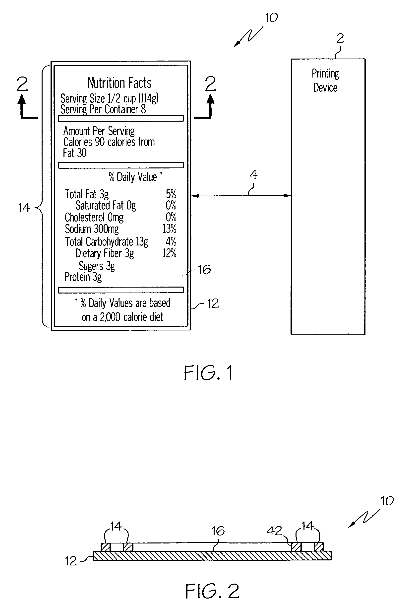
[0027]FIGS. 1 and 2, illustrate a preferred embodiment of the present invention in which an image replication element 10 comprises a support assembly or base 12 supporting a raised relief image 14 on its surface 16. As illustrated schematically in FIG. 1, the image replication element is preferably mounted as a printing plate on a printing device 2 to print the relief image on a provided substrate, such as for example a web or sheet of paper, plastic, foil or the like. After use, the image replication element 10 may be readily demounted from the printing device 2. As the mounting and demounting processes of the image replication element, which is indicated by the numeral 4, are conventional in the art, no further discussion is provided.

[0028]Although, the image replication element 10 of the present invention may be utilized as a flexographic printing plate, it is to be appreciated that with suitable modifications, the image replication element may also be useful in other direct and ...


PUM


Abstract

A process and system for making an image replication element from a photosensitive printing element by digital photopolymerization are provided. The process includes forming a desired printing image on a photopolymer layer by digital light processing without the use of either a mask layer or a laser.

Description

[0001]The present invention relates to printing, and more particularly to a method and associated apparatus for producing by digital light processing an image replication element usable for graphic arts reproduction such as, for example, a flexographic printing plate.[0002]Flexography, also known as aniline printing, is a form of raised printing that utilizes a flexible plate and quick drying inks. The flexible plate is usually made from soft rubber or polymers and carries a relief image that is slightly raised, inked and then transferred directly to a substrate material. This printing method is a high speed process used for extra large print runs and is well suited for a wide variety of substrate materials including acetate film, polyethylene, brown paper and newsprint.[0003]Flexographic printing plates can be prepared using photopolymerizable compositions, such as for example those described in U.S. Pat. No. 4,323,637 (Chen et al) to form relief images. The photopolymerizable comp...

Claims


Application Information

Patent Timeline
IPC IPC(8): B41C1/02B41N1/06B41N1/12
CPCB41C1/02B41N1/06B41N1/12G03F7/2057G03F7/2012
Inventor MCLEAN, MICHAEL E.SCHERRMAN, BRETTNECKERS, DOUGLAS C.SERGUIEVSKI, PETER
Owner DAY INT
Why Eureka
Try Eureka