Antenna device
a technology of antenna coil and antenna coil, which is applied in the direction of loop antennas with ferromagnetic cores, electric devices, transmission, etc., can solve the problems of inability to generate a large loop magnetic flux, excessive directivity of wound coil antennas, and serious problems such as the arrangement of antennas, so as to achieve the effect of reducing increasing the communication distance from an opposing antenna, and widening the directivity of the antenna coil
- Summary
- Abstract
- Description
- Claims
- Application Information
AI Technical Summary
Benefits of technology
Problems solved by technology
Method used
Image
Examples
first embodiment
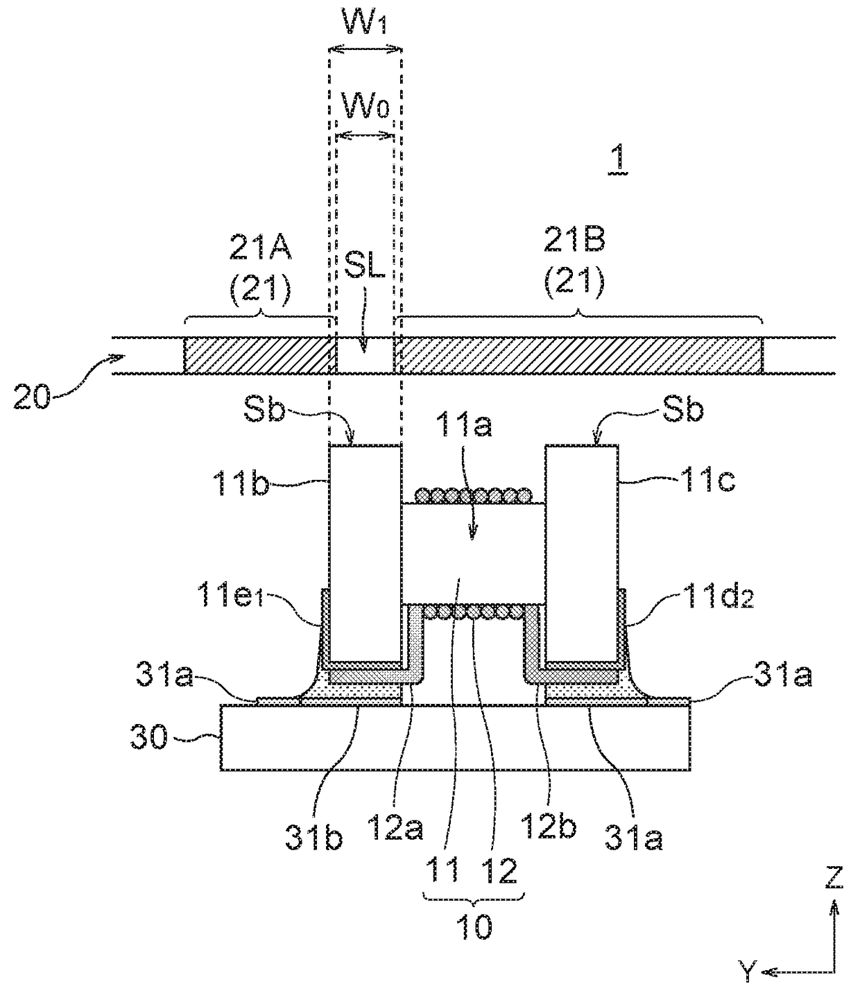
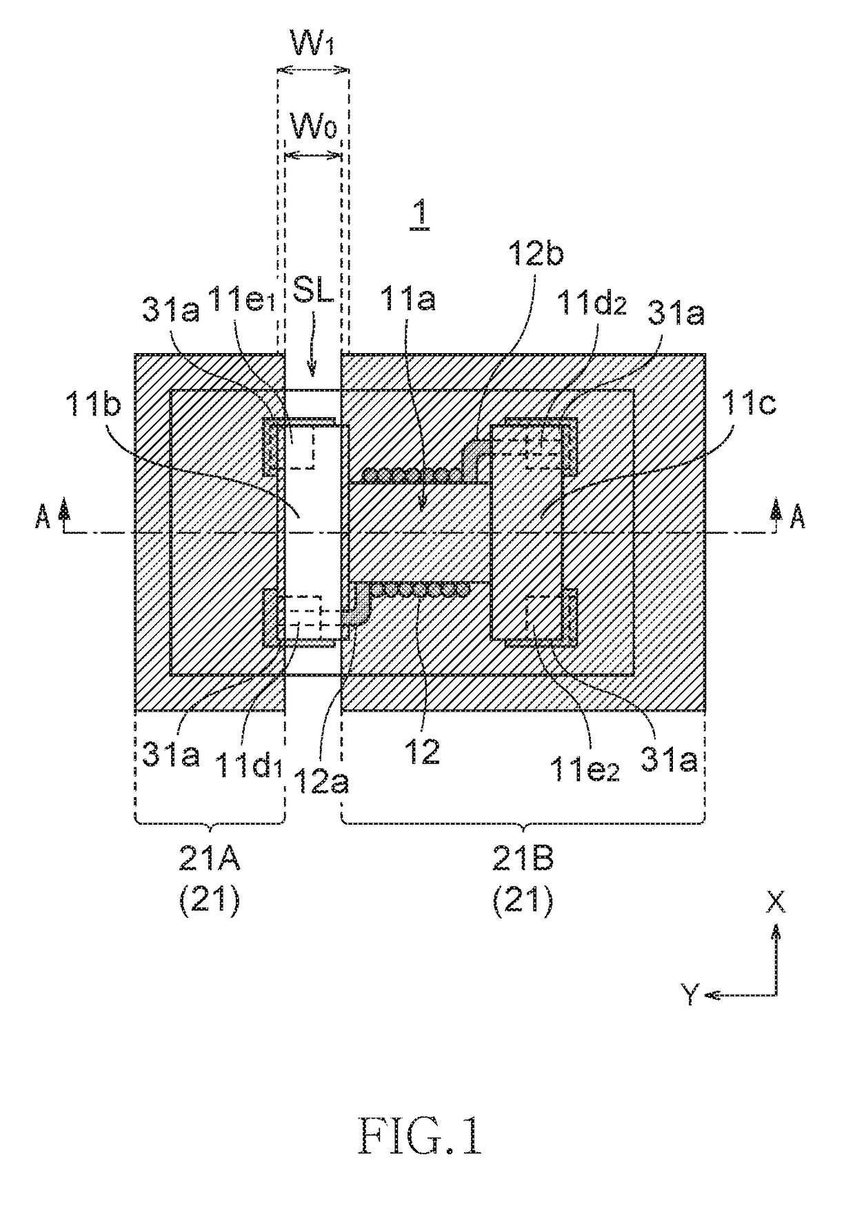
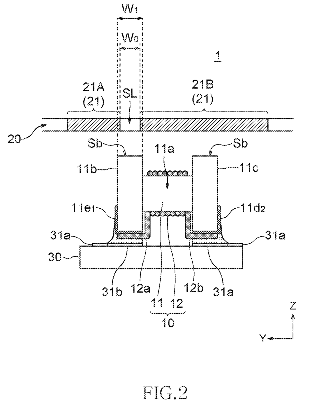
[0027]FIG. 1 is a schematic plan view transparently illustrating a configuration of an antenna device according to the present invention, and FIG. 2 is a schematic cross-sectional side view of the antenna device taken along a line A-A of FIG. 1.
[0028]As illustrated in FIGS. 1 and 2, an antenna device 1 has a wound-type antenna coil 12 wound around a drum-shaped magnetic core 11 and a metal layer 21 covering from above the antenna coil 12. The magnetic core 11 and the antenna coil 12 constitute a surface-mountable wound-type coil component 10. The metal layer 21 constitutes a casing 20 of a mobile electronic device and is disposed substantially parallel to a coil axis (Y-axis) of the antenna coil 12. It is assumed that the metal layer 21 side is positioned above the antenna coil 12, and a side opposite to the metal layer 21 is positioned below the antenna coil 12.
[0029]The magnetic core 11 has a winding core 11a and a pair of flanges 11b and 11c provided at one and the other ends of ...
second embodiment
[0041]FIG. 4 is a schematic cross-sectional view illustrating a configuration of an antenna device according to the present invention.
[0042]As illustrated in FIG. 4, an antenna device of the present embodiment is featured in that a distance H1 from the upper end surface Sb of the first flange 11b that is opposed to the metal layer 21 to the metal layer 21 is smaller than a distance H2 from the upper end surface Sb of the second flange 11c to the metal layer 21. To realize such a configuration, in the present embodiment, a width W3 of the second flange 11c in the Z-direction perpendicular to an extending direction (X-direction) of the slit SL is made smaller than a width W2 of the first flange 11b in the Z-direction. Other configurations are the same as those of the first embodiment.
[0043]When the distance H1 from the upper end surface Sb of the first flange 11b to the slit SL is small, much of the magnetic flux φ emitted from the first flange 11b can be delivered into the slit SL, w...
third embodiment
[0044]FIG. 5 is a schematic cross-sectional view illustrating a configuration of an antenna device according to the present invention.
[0045]As illustrated in FIG. 5, an antenna device 3 of the present embodiment is featured in that, as in the case of the second embodiment, the distance H1 from the upper end surface Sb of the first flange 11b that is opposed to the metal layer 21 to the metal layer 21 is smaller than the distance H2 from the upper end surface Sb of the second flange 11c to the metal layer 21. However, the third embodiment differs from the second embodiment in that the first flange 11b and the second flange 11c have the same size and in a flange mounting position with respect to the winding core 11a. The first flange 11b is mounted to the winding core 11a in a deviated way such that the upper end surface Sb relatively comes close to the metal layer 21 and, conversely, the second flange 11c is mounted to the winding core 11a in a deviated way such that the upper end su...
PUM
 Abstract
Description
Claims
Application Information
 - R&D
- Intellectual Property
- Life Sciences
- Materials
- Tech Scout
- Unparalleled Data Quality
- Higher Quality Content
- 60% Fewer Hallucinations
Browse by: Latest US Patents, China's latest patents, Technical Efficacy Thesaurus, Application Domain, Technology Topic, Popular Technical Reports.
© 2025 PatSnap. All rights reserved.Legal|Privacy policy|Modern Slavery Act Transparency Statement|Sitemap|About US| Contact US: help@patsnap.com


