Antenna device

a technology of an antenna and a magnetic field, applied in the direction of transformers/inductances, magnetic cores of transformers/inductances, instruments, etc., can solve the problems of inability to generate a large loop magnetic flux, the directivity of wound-type coil antennas is excessive, and the arrangement of antennas becomes a serious problem, so as to ensure a magnetic path stably, prevent the effect of deterioration of antenna characteristics and stably ensure the effect o

Active Publication Date: 2018-02-27
TDK CORPARATION
View PDF9 Cites 0 Cited by
  • Summary
  • Abstract
  • Description
  • Claims
  • Application Information

AI Technical Summary

Benefits of technology

[0011]According to the present invention, a magnetic flux generated from the antenna coil can be radiated outside the metal layer through the slit and widely circulated around the metal layer. Thus, directivity of a wound-type antenna coil can be widened, whereby it is possible to realize antenna characteristics suitable for near field communication.
[0018]According to the present invention, it is possible to provide an antenna device having wide directivity and suitable for near field communication even when the wound-type coil antenna is adopted.

Problems solved by technology

When the metallic shield is arranged over a wide range, arrangement of the antenna becomes a serious problem.
However, the wound-type coil antenna has excessively strong directivity.
In addition, when the wound-type coil antenna is reduced in size, it cannot generate a large loop magnetic flux that can be interlinked with an opposing antenna.
Thus, the wound-type coil antenna has problems for practical use as an antenna for near field communication.
When the casing of the mobile electronic device, in which the antenna device is incorporated, is formed of the metal layer, durability and designability of the mobile electronic device can be improved; however, the antenna device cannot perform communication due to a shield effect of the metal layer.

Method used


Image

  • Antenna device
  • Antenna device
  • Antenna device

Examples


first embodiment

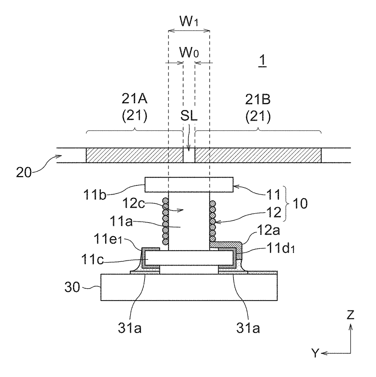
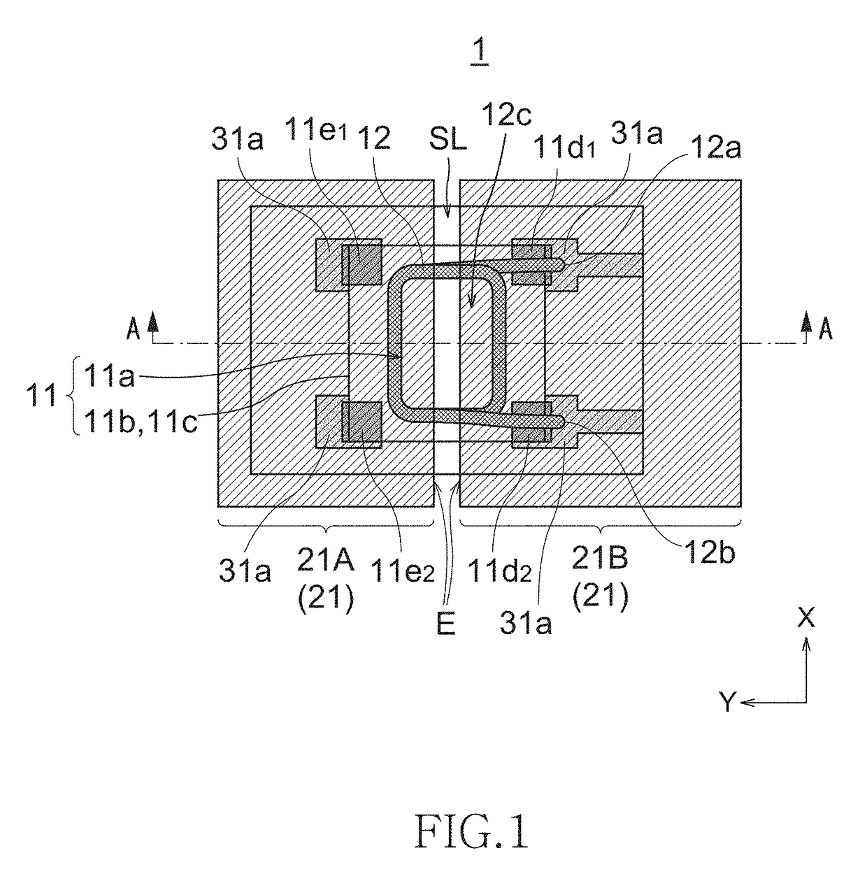
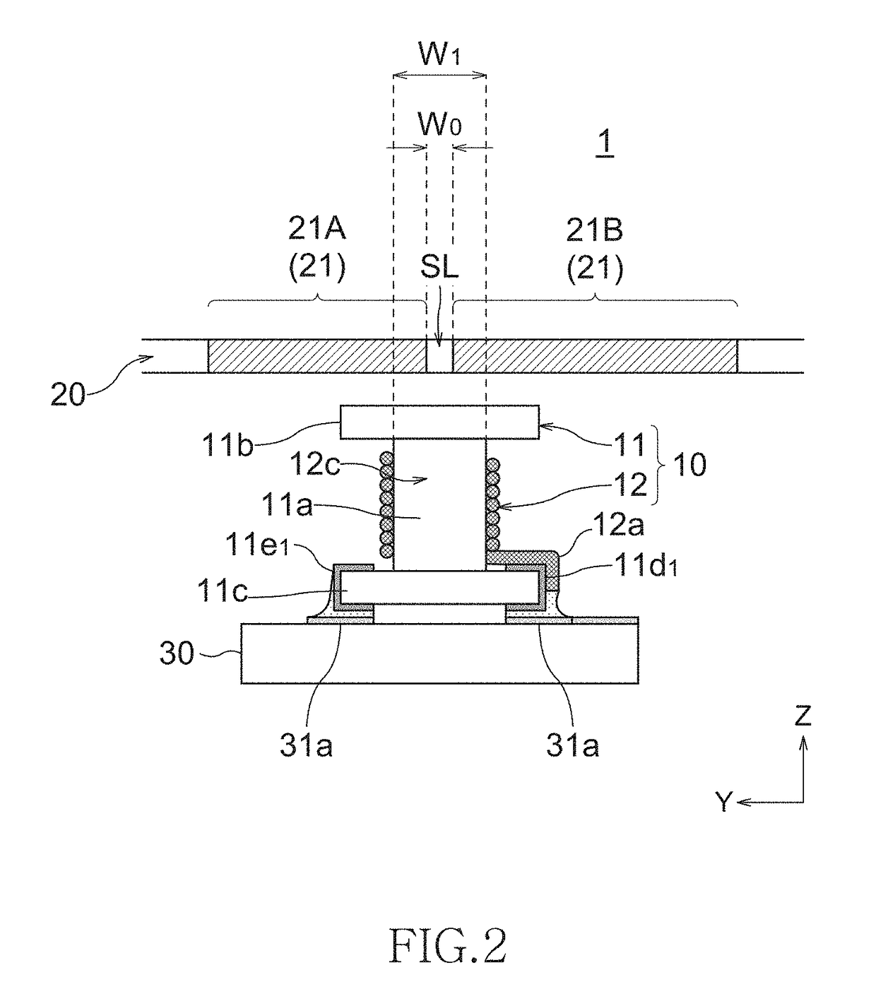
[0028]FIG. 1 is a schematic plan view transparently illustrating a configuration of an antenna device according to the present invention, and FIG. 2 is a schematic cross-sectional side view of the antenna device taken along a line A-A of FIG. 1.

[0029]As illustrated in FIGS. 1 and 2, an antenna device 1 has a wound-type antenna coil 12 wound around a drum-shaped magnetic core 11 and a metal layer 21 covering from above the antenna coil 12. The magnetic core 11 and the antenna coil 12 constitute a surface-mountable wound-type coil component 10. The metal layer 21 constitutes the entire or a part of a casing 20 of a mobile electronic device and is disposed perpendicular to a coil axis (Z-axis) of the antenna coil 12 in a plan view. It is assumed that the metal layer 21 side is positioned above the antenna coil 12, and a side opposite to the metal layer 21 is positioned below the antenna coil 12.

[0030]The magnetic core 11 has a winding core 11a and a pair of flanges 11b and 11c provided...

second embodiment

[0042]FIG. 5 is a schematic cross-sectional view illustrating a configuration of an antenna device according to the present invention.

[0043]As illustrated in FIG. 5, an antenna device 2 of the present embodiment is featured in that the first flange 11b is smaller in size than the second flange 11c. More specifically, an area of an outer side surface Sb of the first flange 11b is smaller than an area of an outer side surface Sc of the second flange 11c. To realize such a configuration, in the present embodiment, a width W2 of the first flange 11b in the Y-direction perpendicular to the extending direction (X-direction) of the slit SL is made smaller than a width W3 of the second flange 11c in the Y-direction. Alternatively, however, a width of the first flange lib in the X-direction may be made smaller than a width of the second flange 11c in the X-direction. Further alternatively, the widths of the first flange 11b in the X- and Y-directions may be made smaller than the widths of th...

third embodiment

[0046]FIG. 6 is a schematic cross-sectional view illustrating a configuration of an antenna device according to the present invention.

[0047]As illustrated in FIG. 6, an antenna device 3 of the present embodiment is featured in that a magnetic sheet 32 larger in size than the second flange 11c is provided at the outer side surface Sb (lower surface) side of the second flange 11c. A width W5 of the magnetic sheet 32 in the Y-direction is larger than a width W4 of the second flange 11c in the Y-direction. A width of the magnetic sheet 32 in the X-direction may be made larger than a width of the second flange 11c in the X-direction.

[0048]Further, in the present embodiment, the second flange 11c of the magnetic core 11 is fixedly bonded to an upper surface of the printed circuit board 30 through the magnetic sheet 32. Further, the one end 12a and the other end 12b of the antenna coil 12 are connected respectively to the pair of signal terminals 11d1 and 11d2 provided on the second flange...


PUM

PropertyMeasurementUnit
heightaaaaaaaaaa
inner diameteraaaaaaaaaa
widthaaaaaaaaaa

Abstract

An antenna device is provided with a magnetic core having a winding core, an antenna coil having a wire wound around the winding core, and a metal layer crossing a coil axis direction of the antenna coil. The metal layer has a slit and an edge of the slit crosses an inner diameter portion of the antenna coil in a plan view.

Description

BACKGROUND OF THE INVENTION[0001]Field of the Invention[0002]The present invention relates to an antenna device and, more particularly, to an antenna device suitable for NFC (Near Field Communication).[0003]Description of Related Art[0004]In recent years, a mobile electronic device such as a smartphone is equipped with an RFID (Radio Frequency Identification: individual identification by radio waves) system and further equipped with, as a communication means of the RFID, an antenna for performing near field communication with a reader / writer and the like.[0005]Further, the mobile electronic device is provided with a metallic shield so as to protect a built-in circuit from external noise and to prevent unnecessary radiation of noise generated inside the device. Particularly, recently, a housing itself of the mobile electronic device is made of metal instead of resin, considering thinness, light weight, durability against drop impact, design, and the like. Cases where the metallic hou...

Claims


Application Information

Patent Timeline
Patent Type & Authority Patents(United States)
IPC IPC(8): H01Q7/00H01F27/28H01F27/24G06K19/077H01Q1/22
CPCH01Q7/00G06K19/07773H01Q1/2225H01F27/28H01F27/24H01F27/292H01F38/14H01F27/36H01F27/363
Inventor KOMACHI, TOSHIFUMIASOU, HIROHUMITOMONARI, TOSHIO
Owner TDK CORPARATION
Why Eureka
Try Eureka