Readily demountable fill valve

a fill valve and easy-to-demount technology, applied in the field of fill valves, can solve the problems of not avoiding the difficulty of access, the need to remove the base with tools, and the difficulty of accessing the valve seat, so as to avoid the possibility of losing parts and facilitate the mounting and demounting

Active Publication Date: 2010-01-19
JOBE HLDG
View PDF11 Cites 13 Cited by
  • Summary
  • Abstract
  • Description
  • Claims
  • Application Information

AI Technical Summary

Benefits of technology

[0022]In the preferred embodiment, to demountably fix the adaptor and valve body, a latch flange is provided on one of the adaptor and the valve body and cooperating latch tabs on the other of adaptor and the valve body, the flange and a mating one of the tabs defining inter-engaging lock surfaces, the lock surfaces being urged toward one another. The latch flange and cooperating tabs may be part of a clamp, latch or like fastener, however the latch flange preferably defines an L-shaped recess of a bayonet joint for receiving each tab to allow the valve body to be connected to the adaptor by a push-twist action. In this manner the fill valve can be readily mounted and demounted, even when the supply of pressurised liquid to the adaptor is maintained. Preferably, the adaptor may be demounted from the valve body by at least partially rotating the valve less than one complete turn, preferably less than a half turn.
[0023]With the valve body, pressure-responsive member and biasing means being arranged such that they are demountable from the adaptor as a unit, once the adaptor is separated from this unit, the seating face on the adaptor can be readily accessed (e.g. for cleaning), as can the mating valve surface. Advantageously this demounting operation can be performed without having to take care to capture and avoid the loss of parts of the valve mechanism.
[0037]The invention provides a fill valve with an adaptor, which can be readily mounted and demounted in a manner so as to provide for access to the opposing seating faces controlling the operation of the valve. Further, with the valve body, pressure-responsive member and biasing means being arranged such that they are demountable from the adaptor as a unit, unnecessary and difficult reassembly and the possibility of losing parts are avoided.

Problems solved by technology

In fill valves, the region including the valve seal and mating valve seating face can become fouled by dirt or debris in the water supply and it may be necessary to remove and disassemble the fill valve to clean this region.
Even if the fill valve can be cleaned or repaired while mounted on the reservoir and still attached to the hardware connecting it, access to the valve and valve seat is difficult and requires the necessary tools to remove the base.
Although the bayonet joint between the valve and the adaptor renders the valve readily mountable and dismountable, it does not avoid the difficulties of accessibility, particularly to the diaphragm of the valve and the mating sealing surfaces controlling operation of the valve itself.
A disadvantage of this design, however is that the screw connection is difficult to release without disconnecting the water supply to the valve.
Additionally, when the base is removed, the spring, diaphragm and other components are not retained, thereby requiring skill and care to avoid loss of these parts and making reassembly of the valve after maintenance troublesome.

Method used


Image

  • Readily demountable fill valve
  • Readily demountable fill valve
  • Readily demountable fill valve

Examples


Embodiment Construction

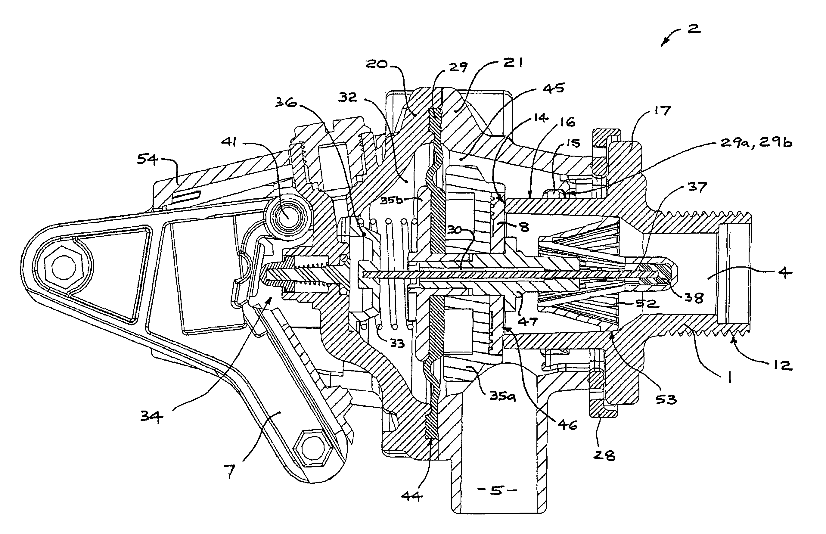
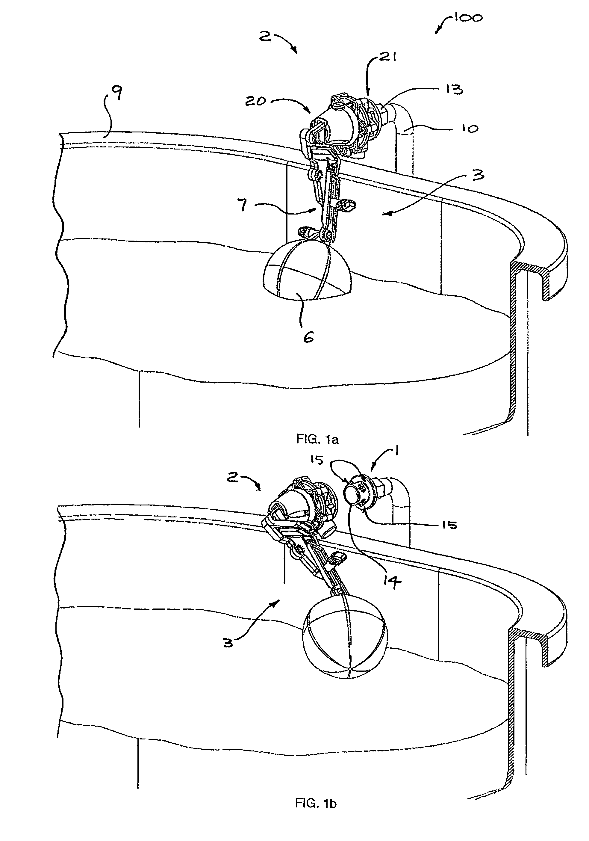
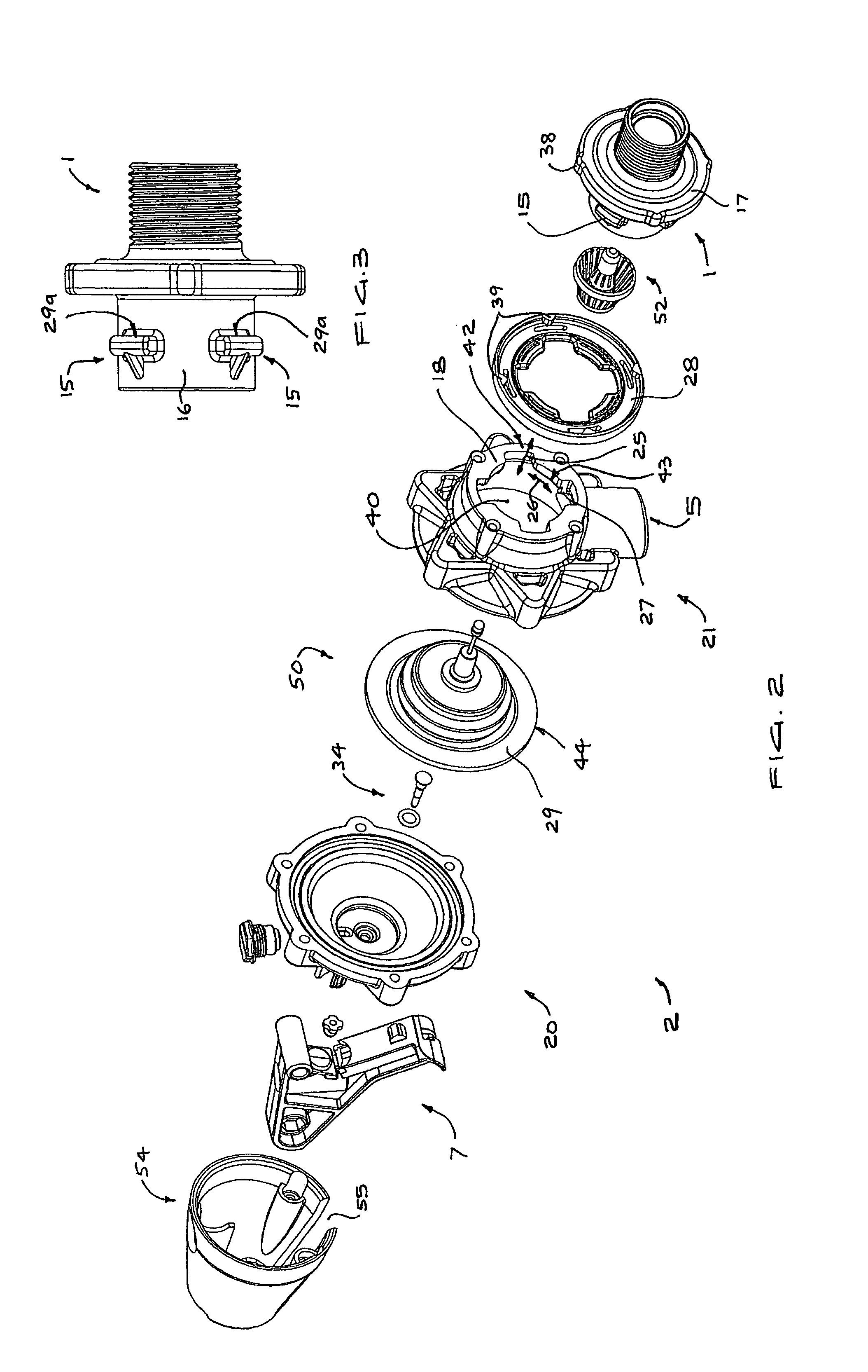
[0044]Referring to the drawings, there is illustrated a fill valve assembly 100 embodying the features of the present invention. The fill valve assembly 100 controls the flow of water into a livestock watering trough 9 to maintains the level of water in at a pre-selected level, refilling the trough 9 to the pre-selected level after the level is lowered. In general, the assembly 100 includes mounting adaptor 1, a valve apparatus 2 and a float assembly 3. The float assembly 3 comprises a control lever 7, one end of which is attached to the valve apparatus 2 and the other to the float 6.

[0045]FIG. 1a illustrates the fill valve assembly 100 connected by the mounting adaptor 1 to a water riser 10 in use. In the position shown, the buoyancy of the ball-shaped float 6 acts to close the valve apparatus 2 to stop water from the riser 10 flowing into the trough 9. FIG. 1b illustrates the manner in which the valve apparatus 2 (and the attached float assembly 3) may be readily demounted from th...


PUM


Abstract

A fill valve assembly for controlling liquid flow into a reservoir includes a mounting adapter defining a liquid inlet passage for connection to a riser for supplying water to the valve and which renders the fill valve readily mountable and demountable for installation and maintenance. A valve body has liquid inlet and outlet openings and a pressure-responsive member is disposed within the valve body and defines a control chamber with which the liquid inlet passage communicates opposite a second side of the pressure responsive member also in communication with the liquid inlet for selectively opening and closing the inlet opening to liquid flow in response to liquid pressure in the control chamber. A biasing means acts on the pressure-responsive member together with pressure in the control chamber, against the inlet pressure acting on the opposite side of the pressure-responsive member, to hold a valve surface fixed to the pressure-responsive member against a valve seating face ion the adaptor so as to close the inlet opening to liquid flow. The valve body, pressure-responsive member and biasing means are arranged to be demountable from the adaptor as a unit in a manner so as to provide ready access to the mating valve surface and valve seating face e.g. for cleaning.

Description

BACKGROUND[0001]1. Field[0002]The present invention relates to fill valves for controlling liquid level in a reservoir. More particularly the invention relates to fill valves having adaptors by which they may be simply and quickly mounted and demounted to allow for simplified installation and maintenance.[0003]2. Description of Related Art[0004]Fill valves function to maintain a predetermined liquid level in a reservoir, and are used widely in livestock watering troughs and toilet tanks. A typical fill valve includes an inlet adapted to be connected to a liquid supply, an outlet communicating with the reservoir, a valve for controlling flow from the inlet to the outlet, a device for detecting the level of liquid in the reservoir (such as a float or diaphragm responsive to water pressure), and means actuated by the detecting device for opening the valve when the liquid level is below a predetermined level.[0005]In fill valves, the region including the valve seal and mating valve seat...

Claims


Application Information

Patent Timeline
Patent Type & Authority Patents(United States)
IPC IPC(8): F16K33/00F16K31/18
CPCE03D1/32F16K31/34F16K31/385Y10T137/053Y10T137/7374Y10T137/7468
Inventor JOBE, DAVIDJOBE, ROBIN
Owner JOBE HLDG
Why Eureka
Try Eureka